Locking mechanism for molded resin component

A locking mechanism and molding technology, applied in the direction of fasteners, electrical components, parts of connecting devices, etc., can solve the problems of deformation of locking retention force or inability to display dimensional errors, etc.

Active Publication Date: 2012-07-04
YAZAKI CORP
View PDF8 Cites 2 Cited by
  • Summary
  • Abstract
  • Description
  • Claims
  • Application Information

AI Technical Summary

Problems solved by technology

In addition, there is a problem that the lock retention force cannot be displayed as designed due to deformation or dimensional error at the time of molding

Method used


Image

  • Locking mechanism for molded resin component
  • Locking mechanism for molded resin component
  • Locking mechanism for molded resin component

Examples


no. 1 example

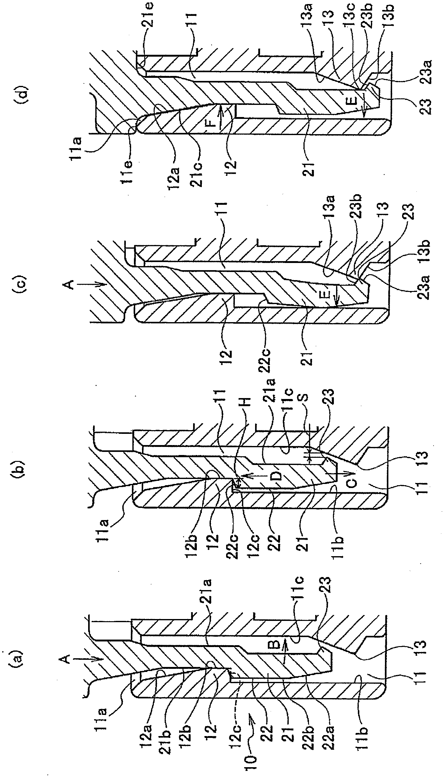
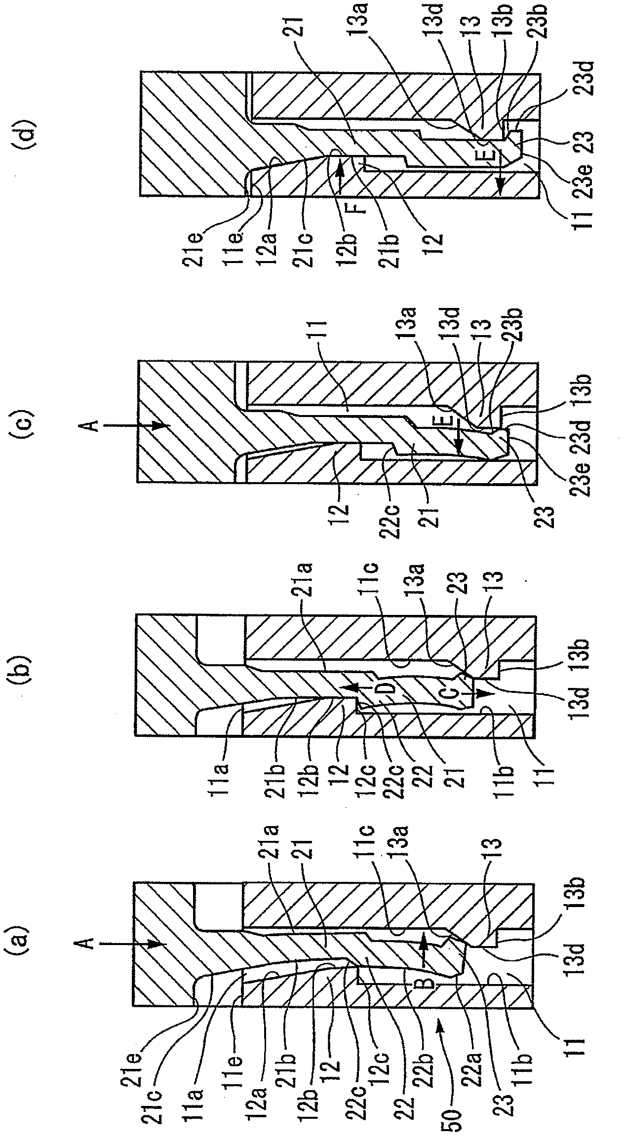
[0052] In the following, reference will be made to figure 1 and figure 2 A first embodiment of the present invention is described.

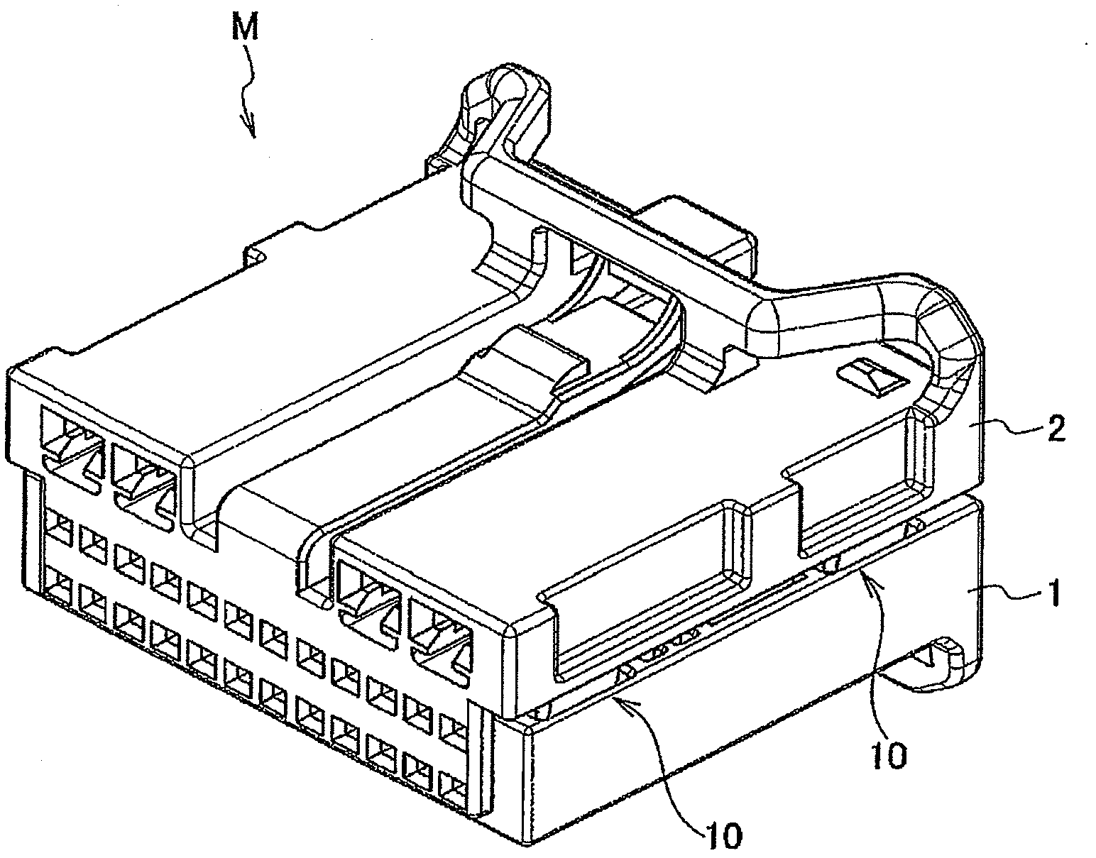
[0053] figure 1 Shows a cross-sectional view of the locking mechanism of the first embodiment of the present invention, showing the sequence of processes collectively elucidating the locking process. figure 1 (a) to figure 1 Multiple states of (d), where (a) shows a state occurring just before a temporary lock, (b) shows a temporary lock state, (c) shows a state occurring just before a permanent lock, and (d) shows the permanently locked state. figure 2 is an external perspective view of a connector employing this locking mechanism.

[0054] like figure 2 As shown, the locking mechanism 10 of the present embodiment is used as a locking means when two housings (resin moldings) 1, 2 are vertically connected together so as to assemble a connector M.

[0055] like figure 1 As shown, the locking mechanism 10 comprises a housing 1 (refe...


PUM


Abstract

Provided is a locking mechanism for a molded resin component, wherein a lock maintaining force can be increased as designed, even when some deformations or dimension errors occur upon molding. A first projecting section (12) for temporary latching is installed in protrusion at a position near an entrance (11a) of a first inner wall face (11b), which is one of two inner wall faces of a locking hole (11) that are opposed to each other, and a second projecting section (13) for the real latching is installed in protrusion on a second inner wall face (11c), at a position deeper than the first projecting section (12). A real-latching protrusion (23), which locks a lock arm (21) to prevent it from coming off, by moving over the second projecting section (13) with a flexion that accompanies an inserting operation of the lock arm (21), and getting engaged with the second projecting section (13) at the getting-over position, is installed in protrusion on a first side face (21a) that faces the second projecting section (13), at the front tip of the lock arm (21). A temporary-latching protrusion (22) is installed in protrusion on a second side face (21b) of the lock arm (21). When the real-latching protrusion (23) is engaged with the second projecting section (13), the first projecting section (12) applies a reaction force to the lock arm (21) in a direction oriented towards the second projecting section (13), by pressing the second side face (21b) of the lock arm (21).

Description

technical field [0001] The present invention relates to a resin molding locking mechanism. Background technique [0002] When combining two resin moldings, a locking mechanism is widely used in which a locking arm having flexibility is formed on one resin molding and a locking protrusion is provided on the other resin molding, which The locking protrusion is adapted to engage with the engaging protrusion on the locking arm by utilizing flexure of the locking arm. [0003] Figure 4 A configuration of a lock mechanism described, for example, in Patent Document 1 is shown. Figure 4 (a) shows the pre-lock state, Figure 4 (b) shows the post-lock state. Reference numeral 120 denotes a lock arm provided on a resin molding, and engaging protrusions 121 are provided at the ends of the lock arm 120 . In addition, a locking protrusion 111 is provided at the locking portion 110 of the other resin molding, and the locking protrusion 111 is adapted to be engaged with the engaging pro...

Claims


Application Information

Patent Timeline
IPC IPC(8): H01R13/639
CPCH01R13/639H01R13/6272H01R13/506H01R13/6271Y10T24/45241Y10T24/45262
Inventor 藤川谅
Owner YAZAKI CORP
Why Eureka
Try Eureka