Light modulator and its fabrication method

一种光调制器、制造方法的技术,应用在仪器、光学、非线性光学等方向,能够解决基板与导电膜接合力弱、导电膜与基板易剥离、光波散射或吸收等问题,达到抑制共振现象或热电效果、抑制热电效果、抑制剥离的效果

Inactive Publication Date: 2008-08-06
SUMITOMO OSAKA CEMENT CO LTD
View PDF4 Cites 6 Cited by
  • Summary
  • Abstract
  • Description
  • Claims
  • Application Information

AI Technical Summary

Problems solved by technology

[0011] However, when the above-mentioned conductive film is formed on the side surface of a thinned substrate (hereinafter referred to as "thin plate"), since the thickness of the substrate is thin and the surface of the side surface of the thin plate is extremely small, the bonding force between the substrate and the conductive film is weak. The disadvantage that the conductive film and the substrate are easily peeled off occurs
[0012] In addition, due to the thinning of the substrate, the confinement of the light wave propagating on the optical waveguide is weakened, resulting in the phenomenon that the light distribution of the light wave expands in the lateral direction (the direction perpendicular to the thickness direction of the thin plate) or the thickness direction of the thin plate. If, when in When a conductive film is formed on the back surface of the substrate, problems such as light waves being scattered or absorbed by the conductive film may occur

Method used


Image

  • Light modulator and its fabrication method
  • Light modulator and its fabrication method

Examples


Embodiment Construction

[0047] Hereinafter, the present invention will be described in detail using appropriate examples.

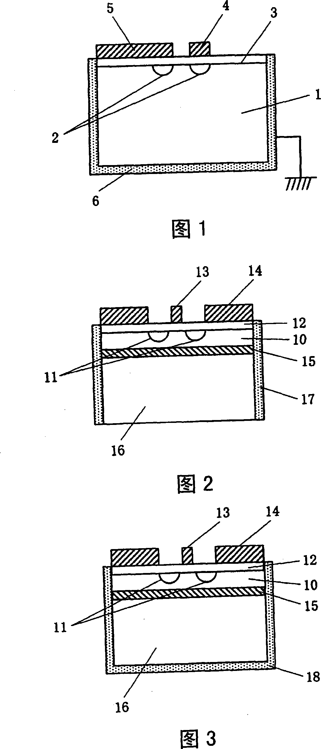
[0048] FIG. 2 is a diagram showing a first embodiment of an optical modulator according to the present invention, showing a cross-sectional view of the optical modulator.

[0049] The light modulator includes: a thin plate 10 with a thickness of 20 μm or less formed of a material having an electro-optical effect; an optical waveguide 11 formed on the surface of the thin plate (the optical waveguide may also be formed on the back of the thin plate 10); and a modulation electrode (signal electrode 13, ground electrode 14), which are formed on the surface of the thin plate, and are used to modulate the light passing through the optical waveguide; the above-mentioned optical modulator is characterized in that it has: a reinforcing plate 16, which is bonded through the layer 15, which is bonded on the back of the thin plate; and a conductive film 17, which is formed continuously from...


PUM


Abstract

It is possible to provide a light modulator using a thin plate having a thickness of 20 mum or below capable of stably holding a conductive film suppressing troubles such as resonance phenomenon of microwaves in a substrate and pyro-electric phenomenon. It is also possible to provide a method for fabricating the light modulator. The light modulator includes: a thin plate (10) formed of a material having a photoelectric effect and having a thickness of 20 mum or below; light waveguide (11) formed on the front or rear surface of the thin plate; and modulation electrodes (13, 14) formed on the front surface of the thin plate for modulating light passing through the light waveguide. The light modulator further includes a reinforcing plate (16) bonded to the rear surface of the thin plate and a conductor film (17) formed on the side surface of the thin plate continuously to the side surface of the reinforcing plate.

Description

technical field [0001] The present invention relates to a light modulator, and more particularly to a light modulator comprising a thin plate and a reinforcing plate, wherein the thin plate is formed of a material having an electro-optical effect and has a thickness of 20 μm or less, and the reinforcing plate is bonded to the back of the thin plate and has a thickness of thicker than the sheet. Background technique [0002] Conventionally, in the field of optical communication or optical measurement, waveguide-type optical modulators in which optical waveguides or modulation electrodes are formed on a substrate having an electro-optical effect have been frequently used. [0003] In an optical modulator using a substrate having an electro-optical effect, as in Patent Document 1 or 2, etc., by forming a conductive film as shown in FIG. The occurrence of the resonance phenomenon that the microwave applied by the device resonates in the substrate, or the pyroelectric effect gen...

Claims


Application Information

Patent Timeline
Patent Type & Authority Applications(China)
IPC IPC(8): G02F1/035
CPCG02F1/035G02F1/2255G02F2201/066G02F2201/127G02F2202/28G02F2203/21
Inventor 神力孝近藤胜利齐藤勉
Owner SUMITOMO OSAKA CEMENT CO LTD
Why Eureka
Try Eureka