Socket connector

A technology of socket connectors and plug connectors, which is applied in the direction of connection, conductive connection, parts of connection devices, etc., can solve the problems that the connection structure of plug connectors and socket connectors cannot be flattened and the height becomes higher, and achieve Improve connection reliability, increase strength, and achieve flattening effects

Inactive Publication Date: 2005-05-11
JST MFG CO LTD
View PDF0 Cites 6 Cited by
  • Summary
  • Abstract
  • Description
  • Claims
  • Application Information

AI Technical Summary

Problems solved by technology

[0004] In this case, since the deformation releasing member rises in the height direction from the top of the partition wall of the receptacle housing, the height of the r

Method used


Image

  • Socket connector
  • Socket connector
  • Socket connector

Examples


Embodiment Construction

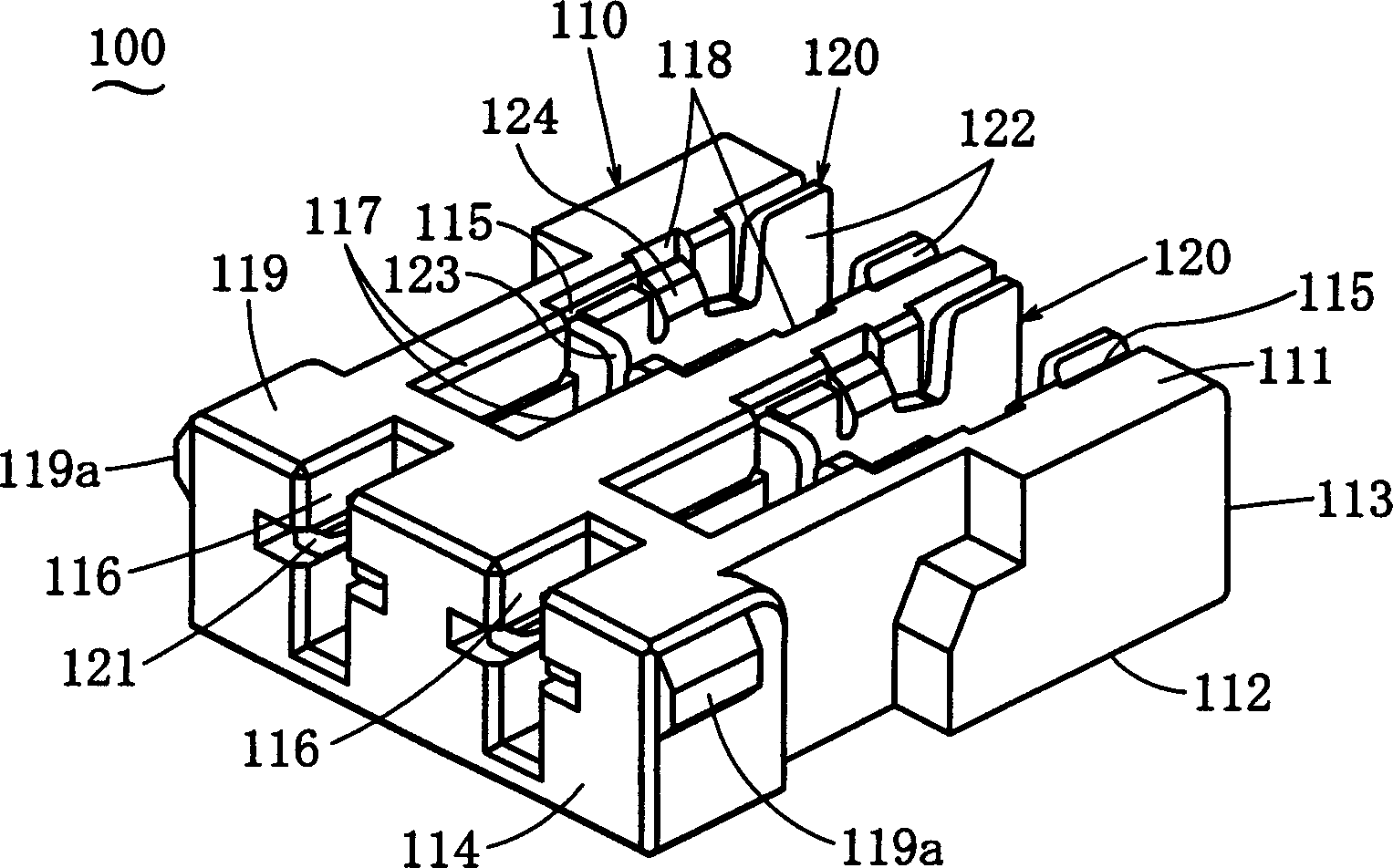
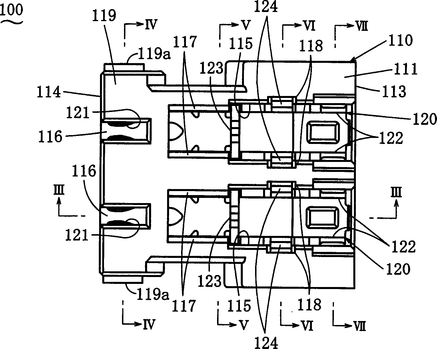
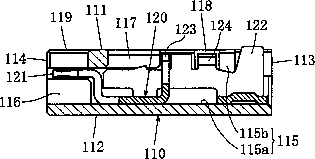
[0034] Hereinafter, examples of the present invention will be described. Figure 1 to Figure 7 Receptacle connector 100 of an embodiment of the present invention is shown. The directions perpendicular to each other are assumed to be the longitudinal direction, the width direction, and the height direction, and the description will be made with reference to these directions. For the case of this example, if combined with figure 2For description, the left-right direction in the figure is the vertical direction, the left side in the figure shows the depth in the vertical direction, and the right side in the figure shows the front in the vertical direction. In addition, a direction perpendicular to the paper surface of the drawing indicates a height direction, and an up-down direction in the drawing indicates a width direction. The receptacle connector 100 has: a receptacle housing 110 formed of an insulating material; and receptacle contacts 120 formed of a conductive material...


PUM


Abstract

A receptacle connector that improves strength against wire (W) stretching and enables flattening of the connection structure. It includes: a socket housing (110), with a wire insertion groove (115) recessed from the back side (111), and a support recess (116) that communicates with the wire insertion groove (115) and opens on the back side (111); The socket contact (120) that enters the wire insertion groove (115); the contact part (121) that contacts the contact (220) in the support recess (116); the insulating barrel (122) and the notch for crimping (123 ), press the electric wire (W) in the insertion groove (115) and crimp it on the cut groove (123), press the sheath of the electric wire (W) with the insulating tube (122), and the installation object (P) When the plug connector (200) is butted, the wire insertion groove (115) of the socket housing (110) is blocked by the installation object (P).

Description

technical field [0001] The invention belongs to the field of electrical connectors, in particular to a socket connector connected with a plug connector installed on the surface of a printed circuit board or other objects to be installed. Background technique [0002] Patent No. 3262732 discloses a crimping connector, which is composed of contacts and insulating housings that touch and connect electric wires, wherein the insulating housing separates the contact receiving chambers through partitions, and the contact receiving rooms are used for separate The contact is isolated and accommodated, the top and the rear end of the housing are opened to press the electric wires, and the partition walls on both sides of the rear end of the opening are provided with deformation releasing members as fixing portions of the electric wires. [0003] When installing the plug connector on the surface of the printed circuit board and connecting the plug connector to the socket connector with...

Claims


Application Information

Patent Timeline
IPC IPC(8): H01R4/24H01R13/11H01R13/115H01R13/58
CPCH01R4/2454H01R13/112H01R13/582H01R13/58
Inventor 森分良堀内秀晃高槻升平
Owner JST MFG CO LTD
Why Eureka
Try Eureka