Communication terminal apparatus, handover control method, and handover control program
A technology of a communication terminal and a control method, which is applied in the field of communication terminal devices and switching control programs, can solve problems such as high price, and achieve the effects of reducing load, reducing switching, and realizing load distribution.
- Summary
- Abstract
- Description
- Claims
- Application Information
AI Technical Summary
Problems solved by technology
Method used
Image
Examples
no. 1 Embodiment approach 〕
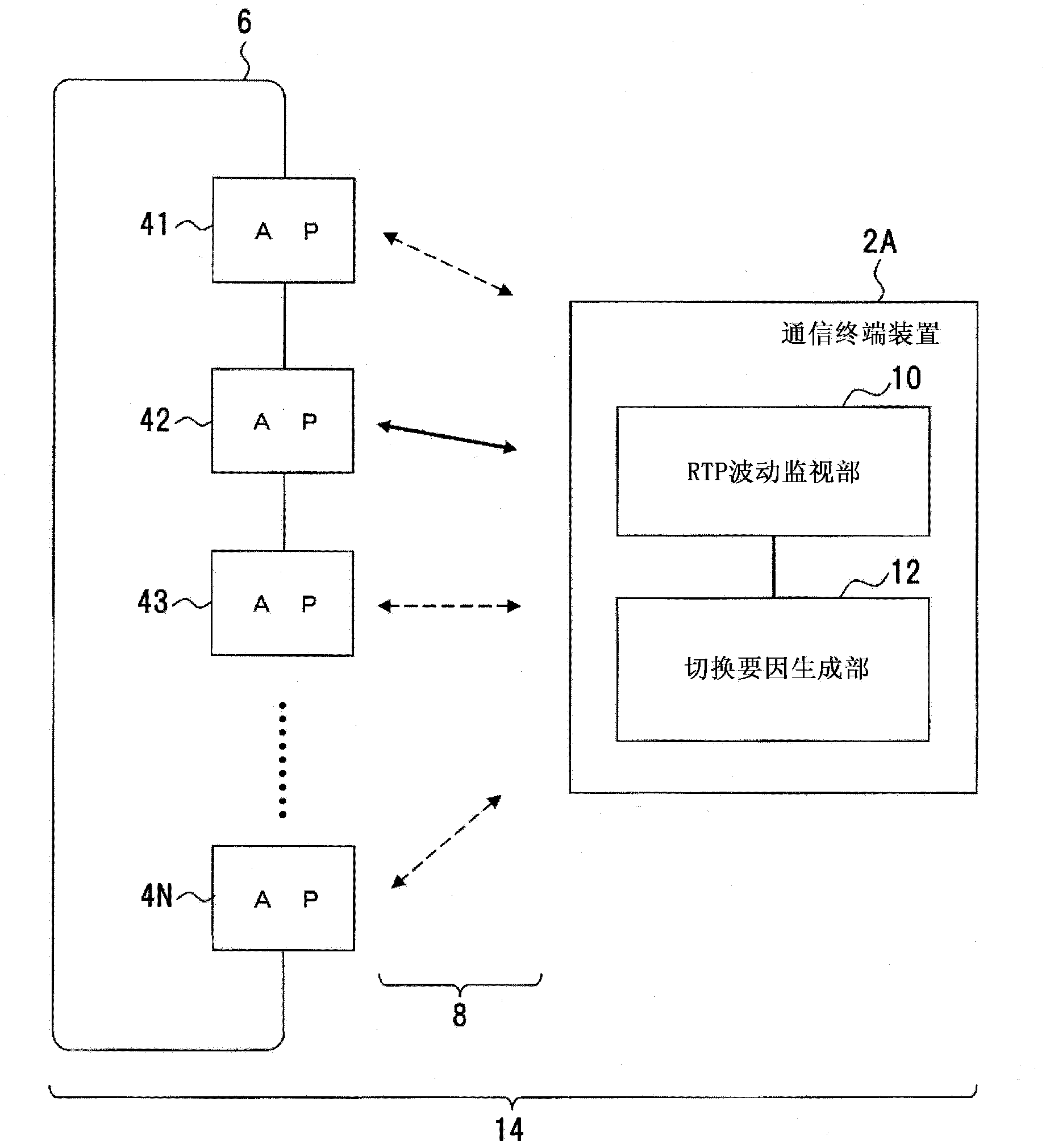
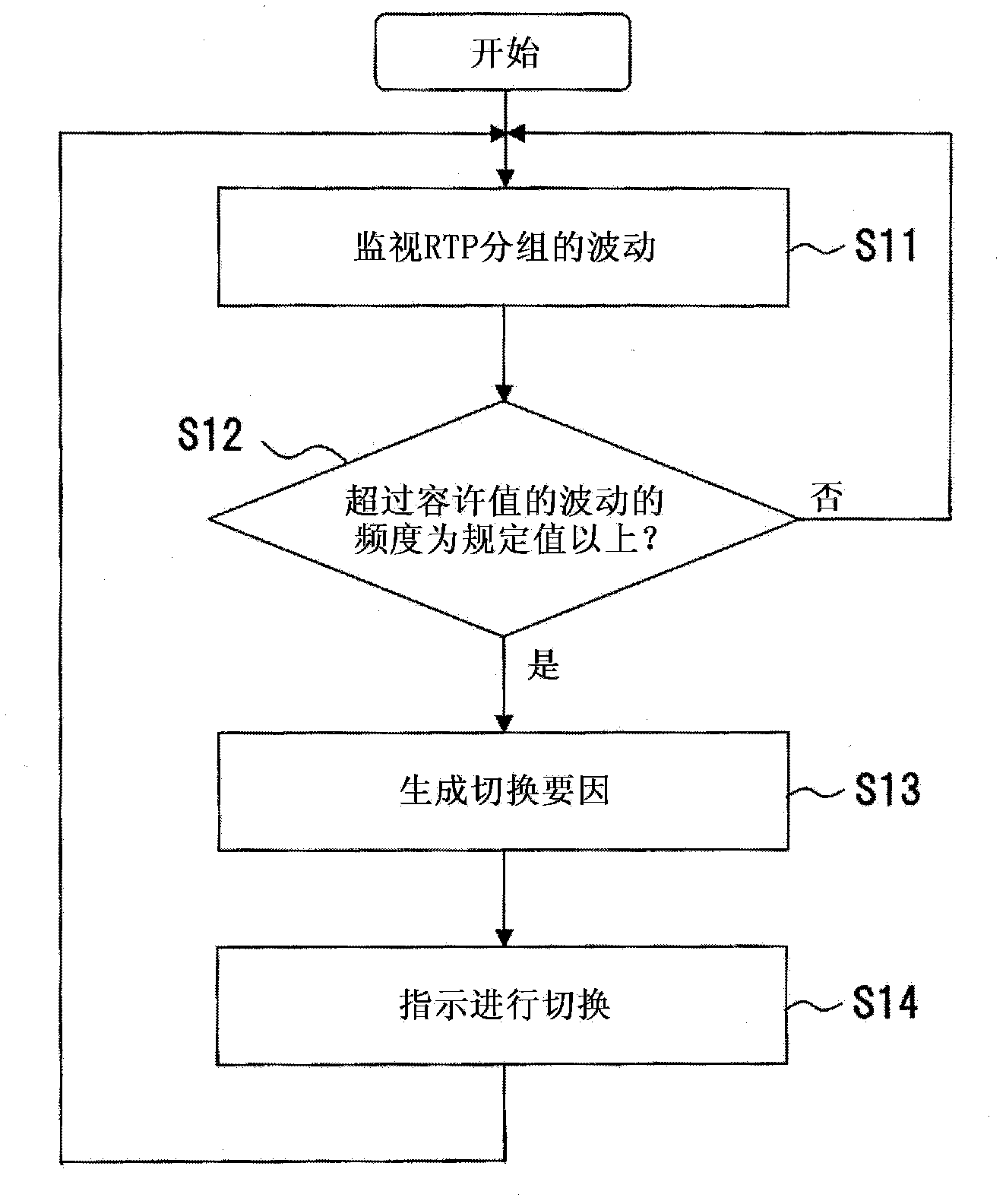
[0052] The configuration of the first embodiment is such that fluctuations in audio data packets are monitored, and switching factors are generated based on the fluctuation frequency.
[0053] For this first embodiment, refer to figure 1 as well as figure 2 . figure 1 It is a figure which shows an example of the communication terminal apparatus of 1st Embodiment, figure 2 It is a flowchart showing the processing procedure of switching factor generation. figure 1 as well as figure 2 The shown structure is just an example, and this structure does not limit this invention.
[0054] The communication terminal device 2A is an example of the communication terminal device, the handover control method, or the handover control program disclosed herein, and is wirelessly connected to any one of the access points (hereinafter referred to as "AP") 41, 42, 43...4N, for example. A mobile phone device, a portable information terminal (PDA: Personal Digital Assistant) and the like that ...
no. 2 Embodiment approach 〕
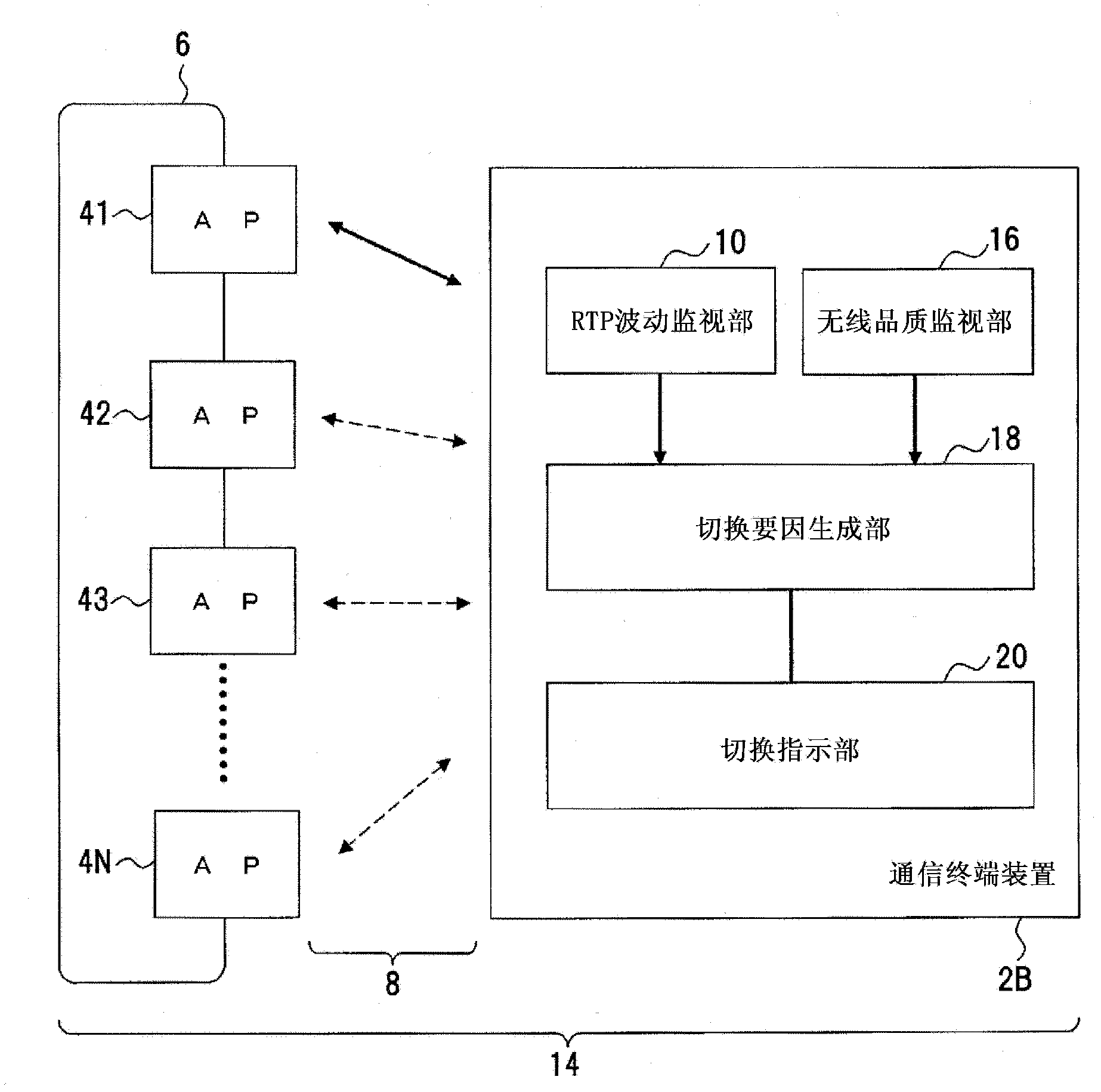
[0064] The configuration of the second embodiment is such that handover is performed using both a handover factor due to degradation of radio quality such as RSSI value degradation and a handover factor corresponding to the fluctuation frequency of RTP packets.
[0065] For this second embodiment, refer to image 3 as well as Figure 4 . image 3 It is a figure which shows an example of the communication terminal apparatus of 2nd Embodiment, Figure 4 It is a flowchart showing the processing procedure of switching factor generation. image 3 as well as Figure 4 The shown structure is only an example, and this structure does not limit this invention.
[0066] In this communication terminal device 2B, a switching factor due to a decrease in radio quality such as an RSSI value and a switching factor corresponding to the fluctuation frequency of RTP packets are used together. Therefore, in this communication terminal device 2B, as image 3 As shown, the fluctuation monitori...
no. 3 Embodiment approach 〕
[0077] The configuration of the third embodiment is configured to monitor degradation of radio quality such as degradation of the RSSI value, generate a switching factor based on the fluctuation frequency of RTP packets, and perform switching. That is, the handover factor is generated based on the logical AND of the decrease in radio quality and the fluctuation frequency of RTP packets.
[0078] For this third embodiment, refer to Figure 5 as well as Figure 6 . Figure 5 is a diagram showing a wireless LAN system, Figure 6 is a graph showing switching around the switching threshold of the RSSI value. Figure 5 as well as Figure 6 The shown structure is just an example, and this structure does not limit this invention.
[0079] In this wireless LAN system 14, as Figure 5As shown, there are a plurality of APs, that is, APs 41, 42, 43...4N, and each AP 41, 42, 43...4N is wirelessly connected to a mobile phone (HS) 201, 202, 203...20N as an example of a communication te...
PUM
 Abstract
Description
Claims
Application Information
 - R&D
- Intellectual Property
- Life Sciences
- Materials
- Tech Scout
- Unparalleled Data Quality
- Higher Quality Content
- 60% Fewer Hallucinations
Browse by: Latest US Patents, China's latest patents, Technical Efficacy Thesaurus, Application Domain, Technology Topic, Popular Technical Reports.
© 2025 PatSnap. All rights reserved.Legal|Privacy policy|Modern Slavery Act Transparency Statement|Sitemap|About US| Contact US: help@patsnap.com


