Cell heat shrink film packaging machine

A heat-shrinkable film and packaging machine technology, which is applied in the field of machinery, can solve the problems of difficult assembly, easy wear of the cam mechanism, and poor work stability, and achieve the effects of low assembly accuracy requirements, simple assembly process, and strong work stability

Active Publication Date: 2013-10-02
NINGBO FUBANG BATTERY
View PDF4 Cites 3 Cited by
  • Summary
  • Abstract
  • Description
  • Claims
  • Application Information

AI Technical Summary

Problems solved by technology

[0007] The heat-shrinkable film conveying mechanism of the heat-shrinkable film packaging machine of the prior art has the following defects: 1. Since the conveying mechanism is driven by a cam mechanism, and the stroke of the cam mechanism is fixed, like this, the movement of the friction plate driven by the cam mechanism The stroke is also fixed, and the distance that the heat-shrinkable film belt driven by the friction plate advances is also fixed. Once the heat-shrinkable film belt advances, it will be cut by the knife head mechanism once, so the heat-shrinkable film that wraps a shrinking battery The length is actually equal to the distance that the heat-shrinkable film belt advances each time. Then, if the length of the heat-shrinkable film wrapping a shrinkable battery is fixed, the length of the shrinkable battery packaged by the battery heat-shrinkable film packaging machine is also fixed. The number of batteries is also fixed, that is, the battery shrink film packaging machine can only pack a fixed length and a fixed number of shrinking batteries, which is poor in versatility; 2. The noise of the cam mechanism is large; 3. The cam mechanism is easy to wear, and once worn, The stroke of the cam is uncertain, so that the length of the heat-shrinkable film wrapping a shrinking battery will not match the design length, and the stroke of the ejector rod driven by the cam mechanism is also uncertain, which will cause the ejector rod to drop too much and damage the The material plate or the ejector pin cannot press the long strip of heat shrinkable film on the feed plate, so the working stability is poor and the service life is short; 4. Since the friction plate is to press the long strip of heat shrinkable film on the transition plate, using friction Force drives the long heat-shrinkable film belt. In this way, the wear is large, the heat-shrinkable film is easily damaged, and the damage rate of parts is also high, which requires frequent maintenance and replacement; The assembly is difficult, because if the friction plate has a deviation in the assembly position, it will not be able to friction drive the long belt of heat shrinkable film, and if there is a deviation in the assembly of the ejector pin, it will not be able to compress the long belt of heat shrinkable film or the ejector pin will drop too much and be damaged If the feeding plate and the film separation frame are not assembled and positioned accurately, it will be difficult to suck the upper and lower sheets of the heat shrinkable film; 6. When the conveying mechanism separates the upper and lower sheets of the heat shrinkable film, it needs to drive the air pump specially , higher energy consumption
[0008] The heat-shrinkable film packaging machine of the prior art also has other defects: the heat-shrinkable film conveying mechanism opens the front end of the heat-shrinkable film long belt and pulls the front end of the heat-shrinkable film long belt to the packaging board. The opening at the front end may shrink due to heat or traction. In this way, when the push plate pushes scattered batteries from the opening of the heat shrinkable film into the cavity of the heat shrinkable film sleeve, the opening at the front end of the heat shrinkable film may be too small and scattered. The condition that the battery cannot enter the cavity of the heat-shrinkable sleeve

Method used


Image

  • Cell heat shrink film packaging machine
  • Cell heat shrink film packaging machine
  • Cell heat shrink film packaging machine

Examples


Embodiment Construction

[0025] The present invention will be further described below in conjunction with the accompanying drawings and specific embodiments.

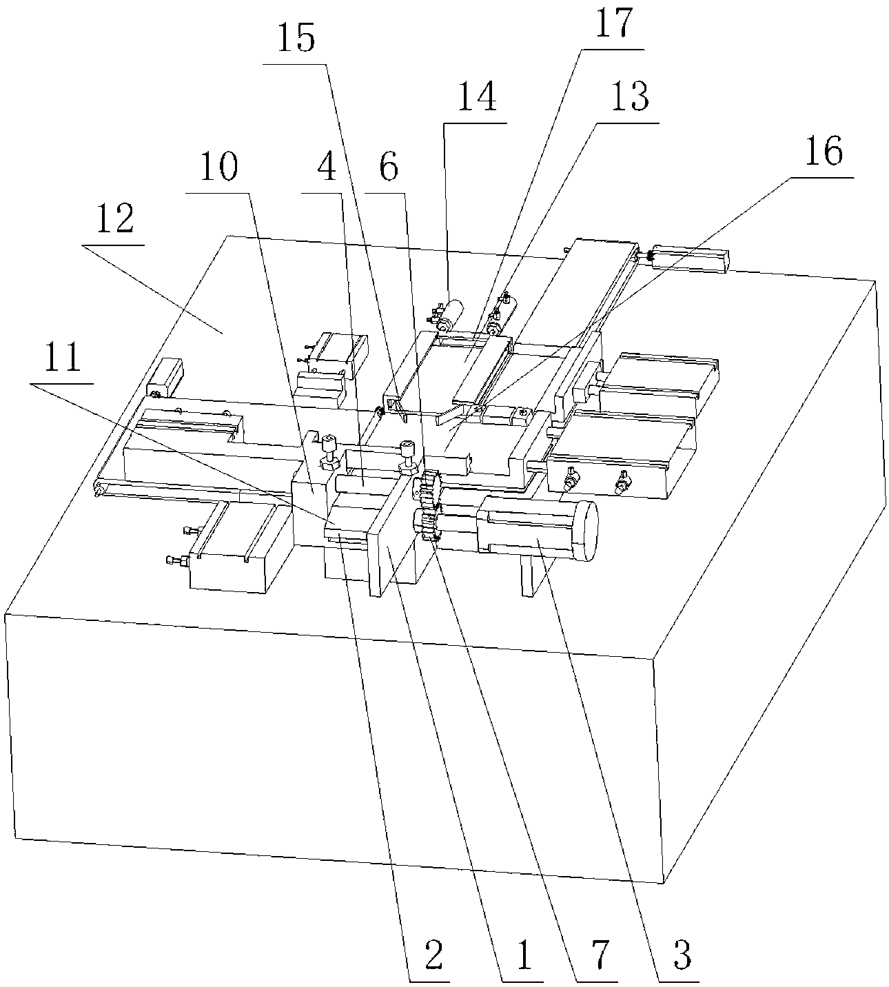
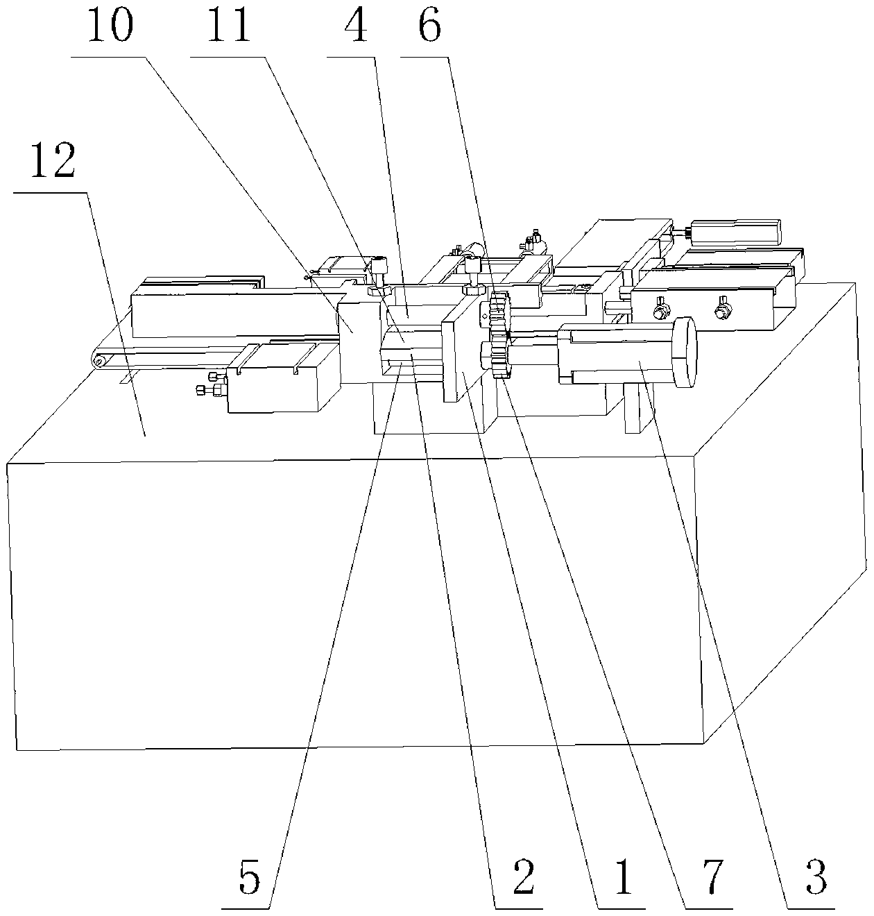
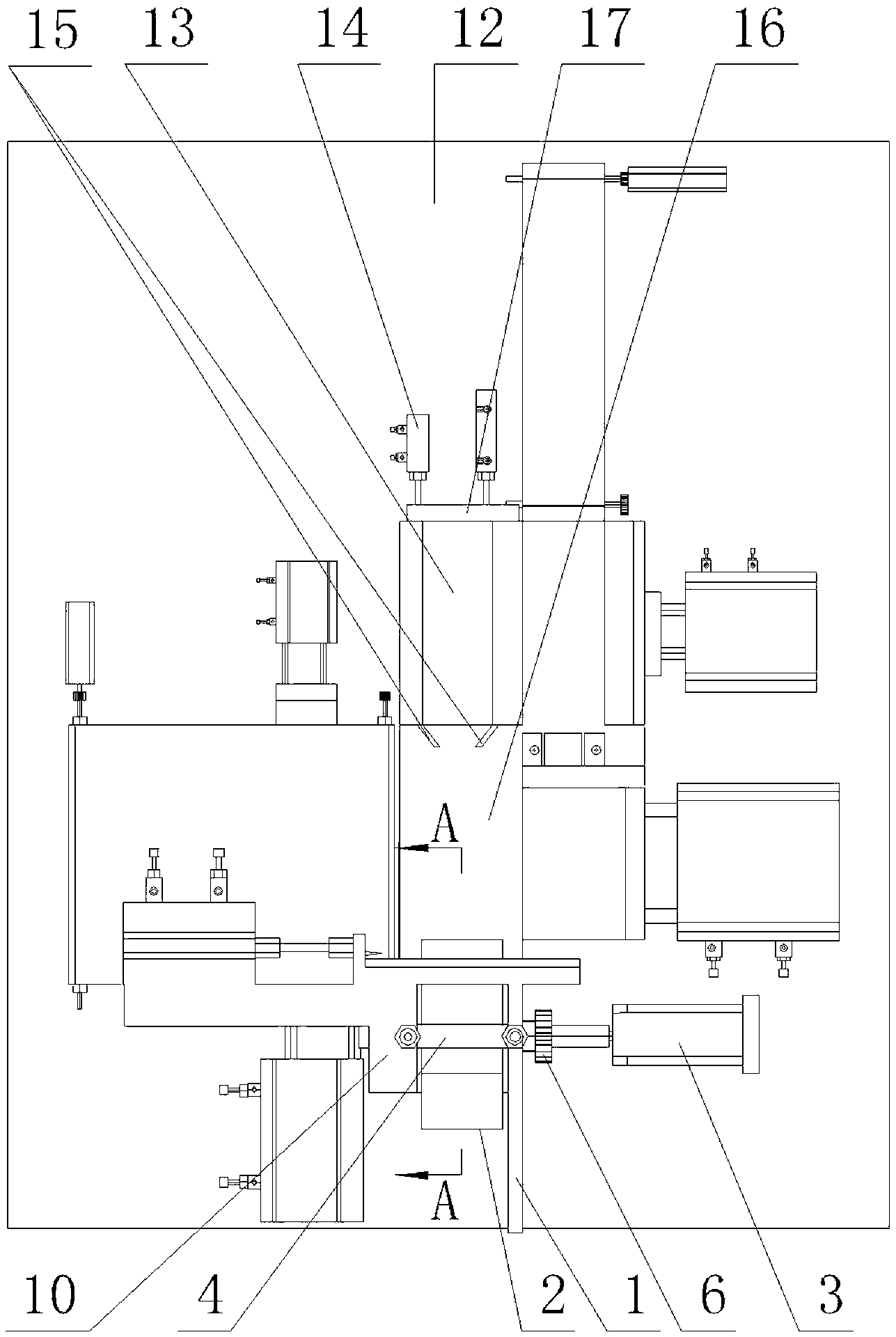
[0026] Such as figure 1 , figure 2 , image 3 , Figure 4 , Figure 5 , Image 6 As shown, the battery heat-shrinkable film packaging machine of the present invention includes a heat-shrinkable film conveying mechanism, and the heat-shrinkable film conveying mechanism includes a first support plate 1, a partition plate 2, a second support plate 10 and a stepping motor 3 . The upper pressing roller 4 and the lower pressing roller 5 are rotatably fitted on the first supporting plate 1 , and the ends of the upper pressing roller 4 and the lower pressing roller 5 away from the first supporting plate 1 can be rotatably fitted on the second supporting plate 10 . The casings of the first support plate 1 , the second support plate 10 and the stepping motor 3 are all fixed on the workbench 12 of the battery shrink film packaging machine. The out...


PUM


Abstract

The invention discloses a cell heat shrink film packaging machine which comprises a heat shrink film conveying mechanism, and the heat shrink film conveying mechanism comprises a first supporting plate (1), a partition plate (2) and a stepping motor (3), wherein an upper compression roller (4) and a lower compression roller (5) are rotatably matched on the first supporting plate (1), an upper gear (6) is fixed at the outer end of the upper compression roller (4), a lower gear (7) is fixed at the outer end of the lower compression roller (5), the upper gear (6) and the lower gear (7) are mutually meshed, and one of the two gears is a gear driven by the stepping motor (3); and two upper rolling wheels are rotatably matched to the upper end face of the partition plate (2), two lower rolling wheels are rotatably matched to the lower end face of the partition plate (2), the two lower rolling wheels under the lower end face of the partition plate (2) are abutted against the circumferential face of the lower compression roller (5), and the circumferential face of the upper compression roller (4) is abutted against the two upper rolling wheels on the upper end face of the partition plate (2). With the cell heat shrink film packaging machine, different lengths and different quantities of various shrink cells can be packed.

Description

technical field [0001] The invention relates to the field of machinery, in particular to a heat shrinkable film packaging machine for batteries. Background technique [0002] The battery heat shrink film packaging machine is a machine that packs scattered batteries into shrinkable batteries with heat shrink film. In the industry, batteries wrapped in a row of heat-shrinkable films are called shrinkable batteries. Heat-shrinkable film is a film that shrinks when exposed to heat and wraps tightly on the product. It is generally made of PVC material. The heat shrinkable film in the industry is a long sleeve. Before use, first flatten the heat-shrinkable film so that the upper and lower pieces of the heat-shrinkable film are tightly attached to form a flat strip, and then the flattened long strip of heat-shrinkable film is rolled into a reel. When in use, pull the heat-shrinkable film strip from the heat-shrinkable film reel, and separate the front end of the heat-shrinkable ...

Claims


Application Information

Patent Timeline
Patent Type & Authority Patents(China)
IPC IPC(8): B65B41/12
Inventor 黄晓飞
Owner NINGBO FUBANG BATTERY
Why Eureka
Try Eureka