Adjusting and detecting device for cutting edge gap of rotary cutter and detecting method thereof

A gap adjustment and detection device technology, which is applied in the direction of shearing devices, measuring devices, electrical devices, etc., can solve the problems of affecting the shearing quality of steel plates and shortening the service life of disc shearing blades, etc., and achieves simple structure and strong use The effect of life and accurate measurement

Inactive Publication Date: 2010-02-17
DALIAN HUARUI HEAVY IND GRP CO LTD
View PDF0 Cites 8 Cited by
  • Summary
  • Abstract
  • Description
  • Claims
  • Application Information

AI Technical Summary

Problems solved by technology

Therefore, this device that requires manual adjustment and detection affects the quality of steel plate shearing, and also shortens the service life of the disc shears.

Method used


Image

  • Adjusting and detecting device for cutting edge gap of rotary cutter and detecting method thereof
  • Adjusting and detecting device for cutting edge gap of rotary cutter and detecting method thereof

Examples


Embodiment Construction

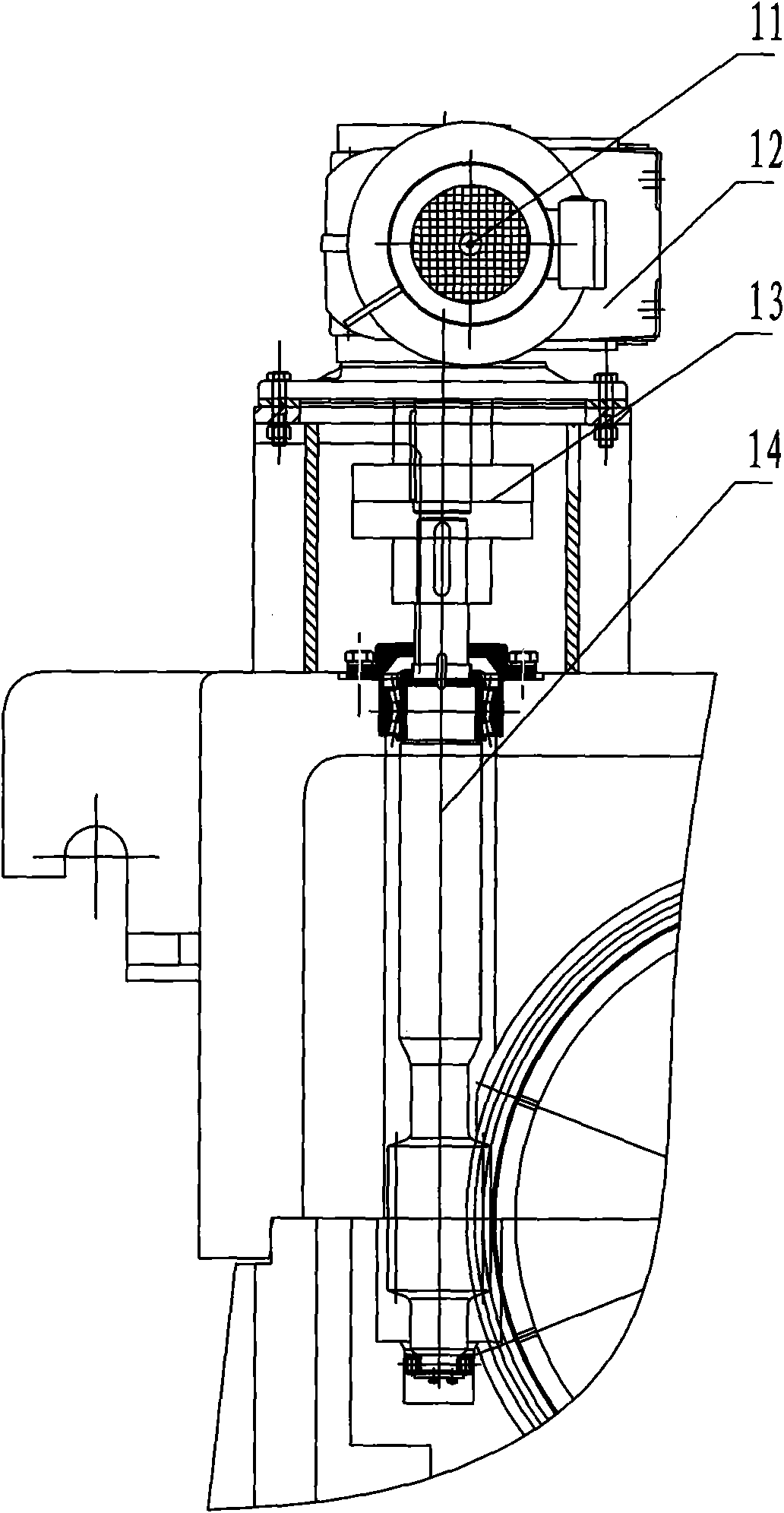
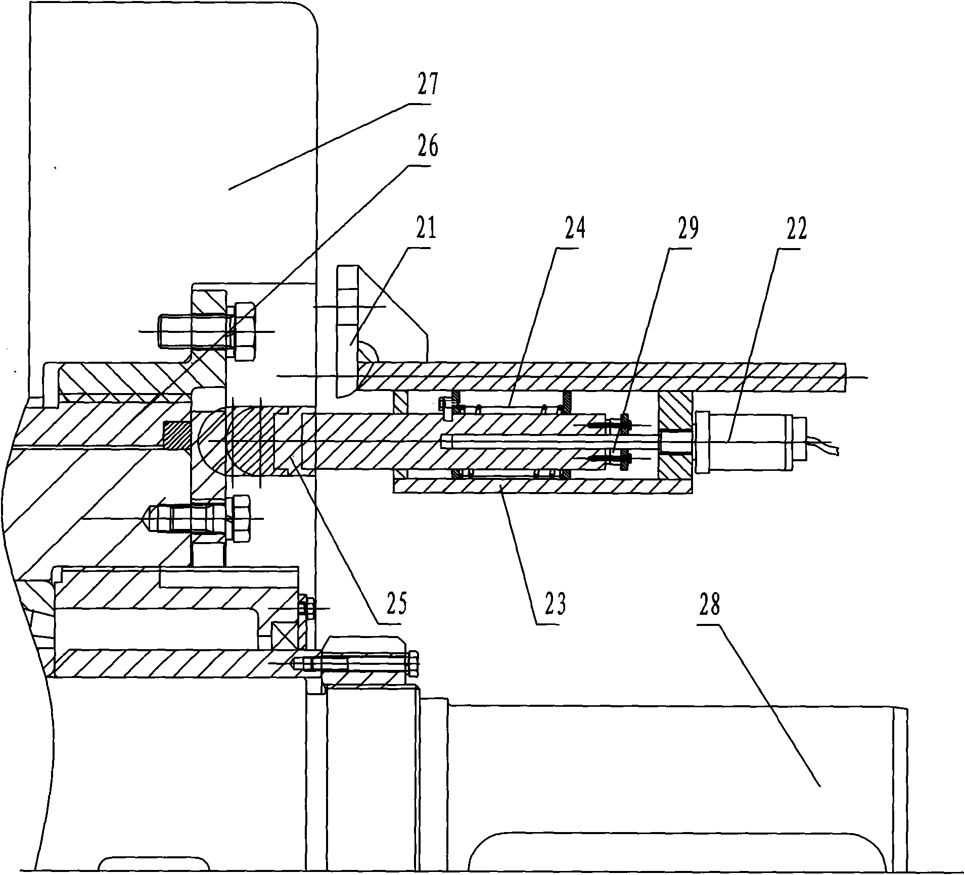
[0021] The present invention will be further described below in conjunction with the drawings. Such as figure 2 As shown, a disc shear blade gap adjustment and detection device is installed on the transmission side of the upper knife shaft assembly 26 of the disc shear. The device includes an upper case 21, a displacement sensor 22, a lower case 23, a spring 24, and a follower Rod 25, the upper box body 21 is mounted on the disc shear body 27 by bolts, the lower box body 23 is connected to the upper box body 21 by bolts, and the upper box body forms a complete closed The box body, the follower rod 25 is tightly pressed on the outside of the upper knife shaft assembly 26 by a spring 24, the displacement sensor 22 itself has a movable magnet 29, which is connected to the upper box body 21 and the lower box by thread At the center of the closed box formed by the body 23, the movable magnet 29 is connected to the follower rod 25 by bolts. The displacement sensor 22 is a digital ...


PUM


Abstract

The invention discloses an adjusting and detecting device for the cutting edge gap of a rotary cutter and a detecting method thereof. The adjusting and detecting device comprises an upper case, a displacement sensor, a lower case, a spring and a follow-up lever, wherein the upper case is installed on the cutting body of the rotary cutter by bolts; the lower case is screwed on the upper case by bolts and forms a complete closed case with the upper case; the follow-up lever tightly presses the outside where an upper cutter shaft is assembled through the spring; the displacement sensor is provided with a movable magnet and is screwed in the central position of the closed case formed by the upper case and the lower case through screw threads; and the movable magnet is screwed on the follow-uplever by bolts. The invention uses the mode that the follow-up lever is assembled and followed up with the upper cutter shaft, causing the movable magnet in the displacement sensor which is screwed onthe follow-up lever to move correspondingly, the moving distance can be read directly through a display meter or an interface card of the displacement sensor, or a controller can be used for operation, and automatic detection and control are realized.

Description

Technical field [0001] The invention relates to a disc shear, in particular to a disc shear blade gap adjustment detection device and a detection method thereof. Background technique [0002] Disc shears play a very important role in the medium and heavy plate steel rolling production line. It is used to cut the two sides of the rolled steel plate to make the steel plate shape and size meet the requirements of the national standard. Whether the adjustment amount of the disc shear blade gap is appropriate or not directly affects the shear quality of the steel plate, which requires a disc shear blade gap adjustment detection device. figure 1 Shown is a schematic diagram of an existing disc shear blade gap adjustment and detection device. Disc shear blade gap adjustment detection is to directly use the encoder 11 at the tail of the transmission reduction motor 12 of the worm gear 14 adjustment mechanism to detect the adjustment gap size of. Due to the influence of the gear backlash...

Claims


Application Information

Patent Timeline
Patent Type & Authority Applications(China)
IPC IPC(8): B23Q17/09B23D19/04G01B7/02
Inventor 邢军蔡金龙侯晓伟
Owner DALIAN HUARUI HEAVY IND GRP CO LTD
Why Eureka
Try Eureka