Turbocharging system with two rotating plates in front of turbine inlet

A technology of turbocharging system and rotating plate, which is applied in the direction of machines/engines, internal combustion piston engines, mechanical equipment, etc., can solve problems such as the complex structure of the turbocharging system, and achieve the effect of simple structure and reasonable design

Inactive Publication Date: 2012-07-11
SHANGHAI JIAO TONG UNIV
View PDF6 Cites 8 Cited by
  • Summary
  • Abstract
  • Description
  • Claims
  • Application Information

AI Technical Summary

Problems solved by technology

[0003] After searching the existing technical literature, it is found that Chinese patent number ZL201020532937.0, patent name: turbocharger device with variable exhaust pipe outlet area, this patent technology provides a device with continuously variable exhaust pipe outlet area , can better take into account the high and low speed conditions of the engine; but the change of the outlet area of ​​the exhaust pipe is realized by the rotation of the rotary handle, which requires adding a special control mechanism to control the rotation of the rotary handle, so that Make the supercharging system structure more complicated

Method used


Image

  • Turbocharging system with two rotating plates in front of turbine inlet
  • Turbocharging system with two rotating plates in front of turbine inlet
  • Turbocharging system with two rotating plates in front of turbine inlet

Examples


Embodiment

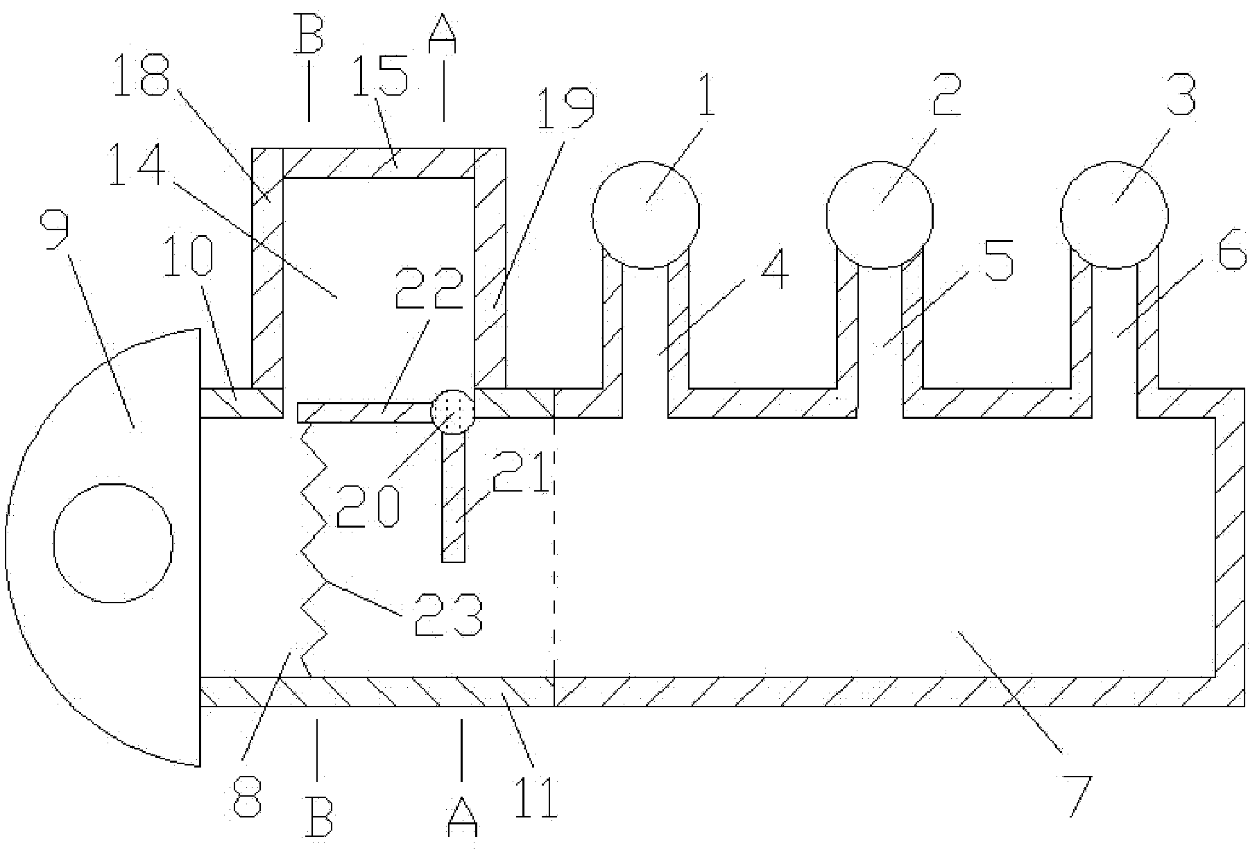
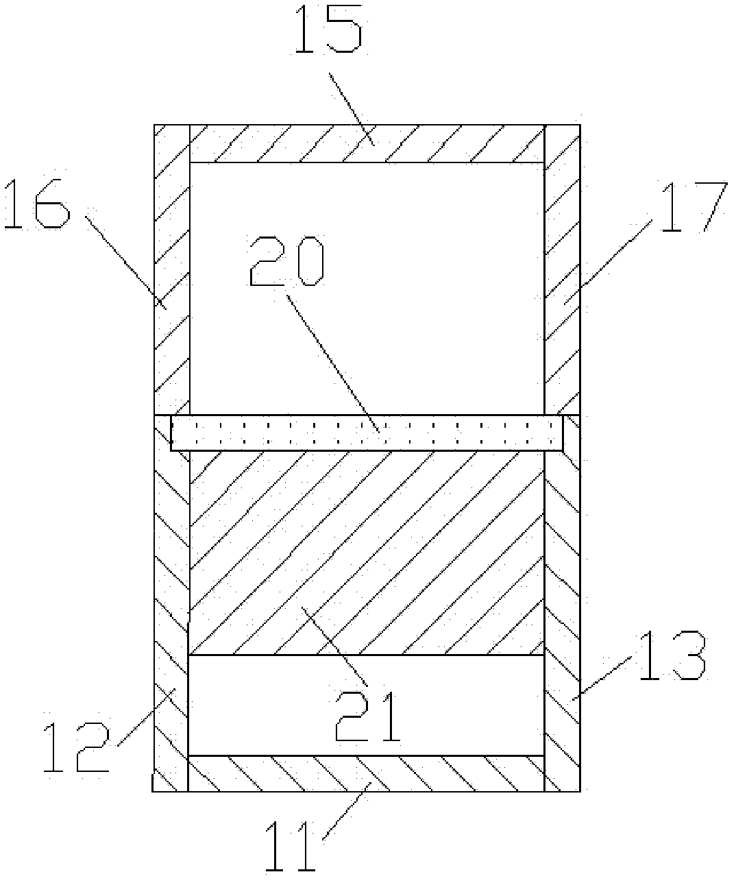
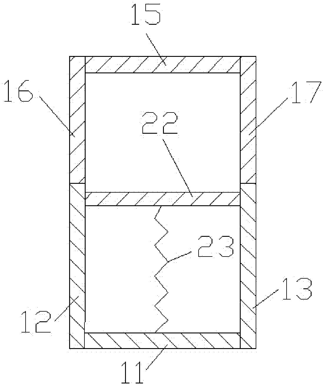
[0015] Such as figure 1 , figure 2 and image 3 As shown, the present invention includes: first cylinder 1, second cylinder 2, third cylinder 3, first exhaust branch pipe 4, second exhaust branch pipe 5, third exhaust branch pipe 6, exhaust pipe 7, connecting pipe 8. Turbine 9, connecting pipe upper wall 10, connecting pipe lower wall 11, connecting pipe front wall 12, connecting pipe rear wall 13, volume chamber 14, volume chamber upper wall 15, volume chamber front wall 16, volume chamber rear wall 17 , volume cavity left wall surface 18, volume cavity right wall surface 19, rotating shaft 20, first rotating plate 21, second rotating plate 22 and elastic member 23, the first cylinder 1, the second cylinder 2, the third cylinder 3 pass through the first cylinder respectively An exhaust branch pipe 4, a second exhaust branch pipe 5, and a third exhaust branch pipe 6 are connected to the exhaust pipe 7, the outlet of the exhaust pipe 7 is connected to the inlet of the connec...


PUM


Abstract

A turbocharging system with two rotating plates in front of a turbine inlet belongs to the technical field of internal combustion engines and comprises a cylinder, an exhaust tube, a connecting tube, a turbine, a capacity cavity, the rotating plates, a rotating shaft and an elastic component. An opening end of the capacity cavity is connected with the upper wall surface of the connecting tube, the rotating shaft is mounted between a front wall surface and a rear wall surface of the connecting tube, both the first rotating plate and the second rotating plate are integrally fixedly connected with the rotating shaft, and the second rotating plate is connected with the lower wall surface of the connecting tube via the elastic component. When an engine is in a high-speed working condition, both the two rotating plates rotate clockwise, the area of a throat of the connecting tube is large, so that pumping loss is low, and performances of the total engine are excellent; and when the engine is in a low-speed working condition, both the two rotating plates rotate anticlockwise, the area of the throat of the connecting tube is small, available energy in front of the turbine is sufficient, air inlet pressure of the engine is high, and the performances of the integral engine are excellent. The turbocharging system is reasonable in design and simple in structure. The invention is applicable to a turbocharging system with a side-mounted turbine at a turbine inlet.

Description

technical field [0001] The invention relates to a turbocharging system in the field of internal combustion engines, in particular to a turbocharging system with two rotating plates in front of a turbine inlet. Background technique [0002] With the development of society and the improvement of environmental protection requirements, the application of engine supercharging technology is becoming more and more extensive. Most of the engines with medium and high power adopt turbocharging technology to improve power and reduce fuel consumption. The two basic types of turbocharging systems are constant pressure supercharging system and pulse supercharging system. Constant pressure supercharging system, each cylinder shares an exhaust pipe with a large volume, the structure of the exhaust pipe system is relatively simple, the pressure in the exhaust pipe is basically kept constant, the pressure is only related to the load and speed of the engine, different cylinder numbers The sup...

Claims


Application Information

Patent Timeline
Patent Type & Authority Applications(China)
IPC IPC(8): F02B37/22
CPCY02T10/144Y02T10/12
Inventor 李华雷邓康耀崔毅石磊
Owner SHANGHAI JIAO TONG UNIV
Why Eureka
Try Eureka