
Electromagnetic valve automatically separating impurities

An automatic separation, solenoid valve technology, applied in the field of solenoid valves, can solve the problems of wasting water resources, manpower maintenance, pipeline tightness, etc., to avoid waste, save manpower consumption, and ensure the stability of use.

Active Publication Date: 2013-12-25
FUJIAN GIBO KITCHEN & BATH TECH CO LTD
View PDF7 Cites 0 Cited by
  • Summary
  • Abstract
  • Description
  • Claims
  • Application Information

AI Technical Summary

Problems solved by technology

And the existing solenoid valve is usually mainly made up of a pipeline and a switching device for controlling the opening or closing of the pipeline. The water inlet end of the solenoid valve pipeline flows into the pipeline and flows to the water outlet end of the pipeline, and then the water flows into the sanitary ware through the water outlet end of the pipeline; It is inevitable that some impurities will be brought in, and some of these impurities will inevitably remain in the pipeline. After long-term accumulation, the impurities trapped in the pipeline will easily block the solenoid valve. Specifically, it will cause the switching device of the solenoid valve to Blocked and stuck by impurities, so that the switch device cannot close the pipeline tightly, and then the solenoid valve can not completely close the water, which not only wastes water resources, affects the use of users, but also requires manpower make repairs

Method used


Image

  • Electromagnetic valve automatically separating impurities
  • Electromagnetic valve automatically separating impurities
  • Electromagnetic valve automatically separating impurities

Examples


Embodiment 1

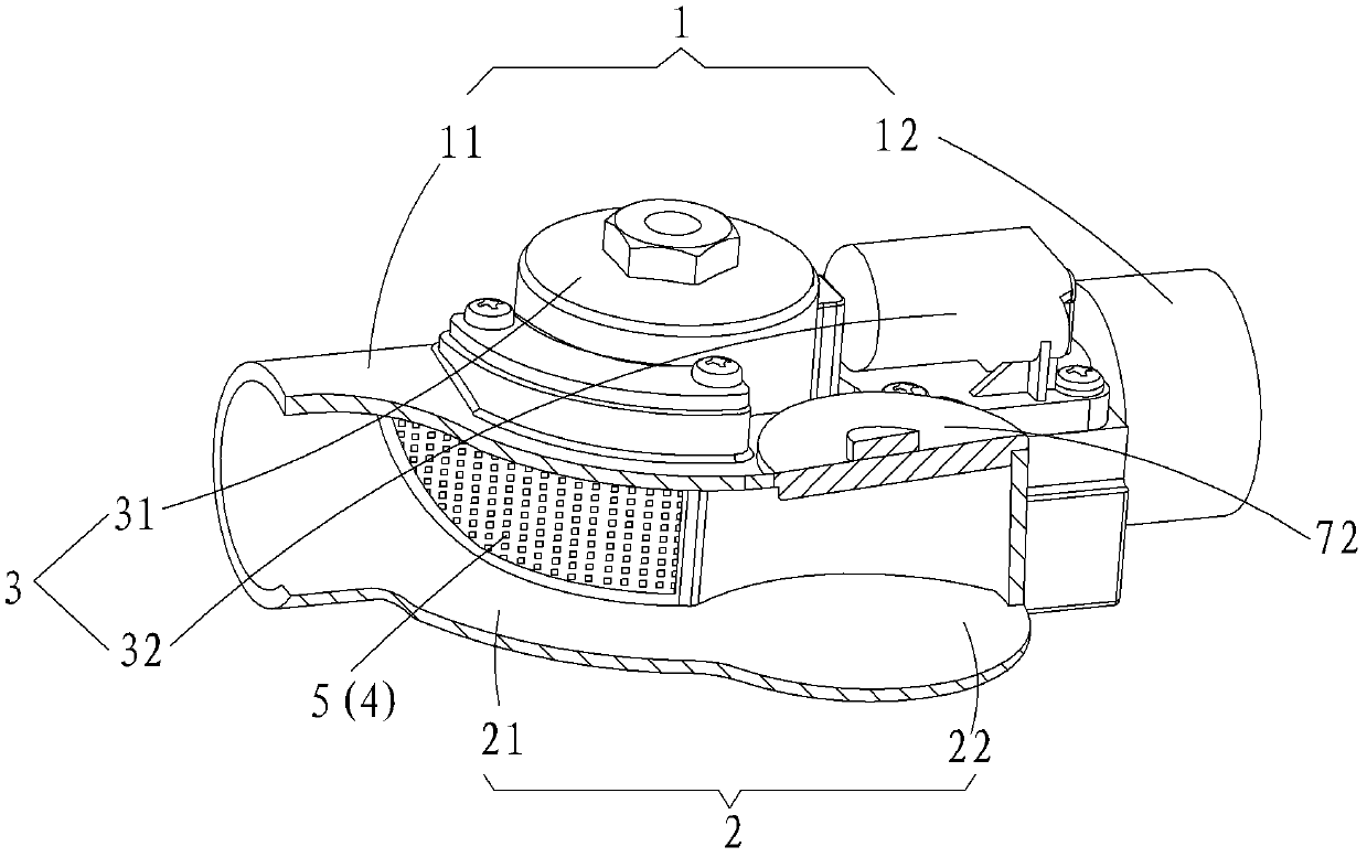
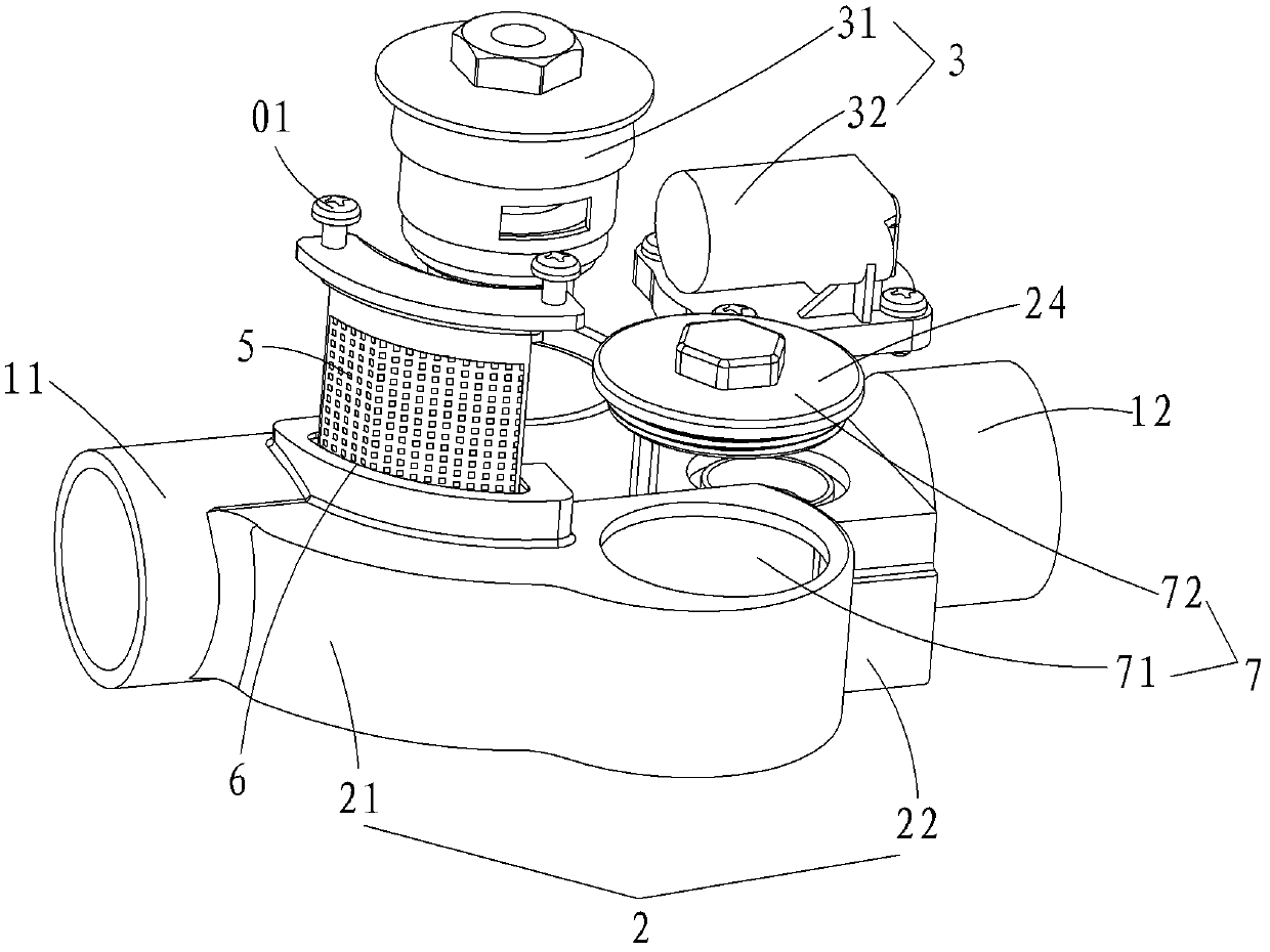
[0022] like figure 1 and figure 2 As shown, the electromagnetic valve of this embodiment includes a main pipeline 1, a pipeline 2, and a switch device 3 for controlling the opening or closing of the main pipeline 1, and the main pipeline 1 includes a water inlet 11 and a water outlet 12. The head end 21 of the branch pipe 2 and the water inlet end 11 of the main pipe 1 are connected and communicated through a first joint 4. The tail end 22 of the branch pipe 2 is a closed end, and the switch device 3 is located at the first joint. On the main pipe 1 between the junction 4 and the water outlet 12, the first junction 4 is provided with an arc-shaped filter screen 5, and the tail end 22 of the branch pipe 2 and the first junction 4 A manual slag removal unit 7 is provided, and the manual slag removal unit 7 includes a slag removal port 71 and a gland 72 for closing the slag removal port 71, the gland 72 is matched with the slag removal port 71, and the slag removal The port 72...

Embodiment 2

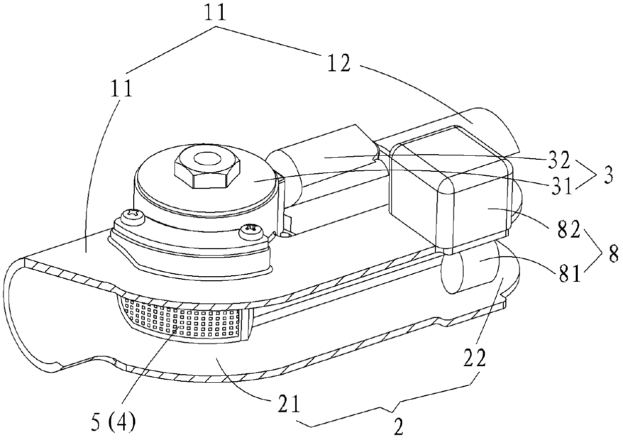
[0026] Please refer to image 3 and Figure 4 , the structure of the solenoid valve in this embodiment is compared with that of Embodiment 1, the difference is that in this embodiment, the slag cleaning unit used is not as figure 1 The shown manual slag removal unit 7 uses an automatic slag removal unit 8 instead; and the tail end 22 of the branch pipe 2 is connected and communicated with the water outlet 11 of the main pipe 1 through a second joint 9 . The automatic slag removal unit 8 includes a slag discharge valve body 81 and an electric control system 82 connected with the slag discharge valve body 81, and the slag discharge valve body 81 is arranged between the first junction 4 and the second junction 9 between. Among them, the electric control system 82 is used to control the opening or closing of the slagging valve body 81. The electric control system 82 can be set in advance so that it can open the slagging valve body 6 every once in a while, and set the slagging va...

Embodiment 3

[0030] Please refer to Figure 5 and Image 6 , the structure of the solenoid valve in this embodiment is actually a combination of Embodiment 1 and Embodiment 2. Specifically, in this embodiment, two slag cleaning valves are provided between the tail end 22 of the branch pipe 2 and the first joint 4. unit, one of which is the manual slag removal unit 7 described in Embodiment 1, and the other slag removal unit is the automatic slag removal unit 8 described in Embodiment 2, and the slag removal unit 7 of the manual slag removal unit is The port 71 is located between the automatic slag cleaning unit 8 and the first connecting point 4 , and the tail end 22 of the branch pipe 2 and the water outlet end 12 of the main pipe 1 are connected and communicated through a second connecting point 9 .

[0031] In the application of this embodiment, when the automatic slag removal unit 8 can be used normally, the automatic slag removal unit 8 can be given priority to remove impurities accu...


PUM


Abstract

The invention provides an electromagnetic valve automatically separating impurities. The electromagnetic valve comprises a main pipeline, a branch pipeline and a switching device for controlling opening or closing of the main pipeline, wherein the main pipeline comprises a water inlet end and a water outlet end; the first end of the branch pipe is jointed and communicated with the water inlet end of the main pipeline by a first jointing part; at least one slag removing unit is arranged between the tail end of the branch pipeline and the first jointing part; the switching device is arranged on the main pipeline between the first jointing part and the water outlet end; and the first jointing part is provided with an arc-shaped filtering valve. The electromagnetic valve has the advantages that the switching device of the electromagnetic valve can be prevented from being blocked and clamped by the impurities, the waste of water resources is saved, and the manpower needed by maintenance is saved; and the impurities can be conveniently removed out of the electromagnetic valve.

Description

【Technical field】 [0001] The invention relates to sanitary equipment, in particular to an electromagnetic valve for automatic separation of impurities. 【Background technique】 [0002] Sensor sanitary products such as automatic sensor faucets and sensor flush valves in the bathroom usually have a solenoid valve as the actuator for switching water. And the existing solenoid valve is usually mainly made up of a pipeline and a switching device for controlling the opening or closing of the pipeline. The water inlet end of the solenoid valve pipeline flows into the pipeline and flows to the water outlet end of the pipeline, and then the water flows into the sanitary ware through the water outlet end of the pipeline; It is inevitable that some impurities will be brought in, and some of these impurities will inevitably remain in the pipeline. After long-term accumulation, the impurities trapped in the pipeline will easily block the solenoid valve. Specifically, it will cause the sw...

Claims


Application Information

Patent Timeline
Patent Type & Authority Patents(China)
IPC IPC(8): F16K27/00B01D35/04
Inventor 李达良郑少波
Owner FUJIAN GIBO KITCHEN & BATH TECH CO LTD
Learn More