Automatic mind control water valve system
An idea control, water valve technology, applied in valve details, valve device, valve operation/release device, etc., can solve the problems of inconvenience and large volume, and achieve the effect of convenient use
- Summary
- Abstract
- Description
- Claims
- Application Information
AI Technical Summary
Problems solved by technology
Method used
Image

Examples
Embodiment 1
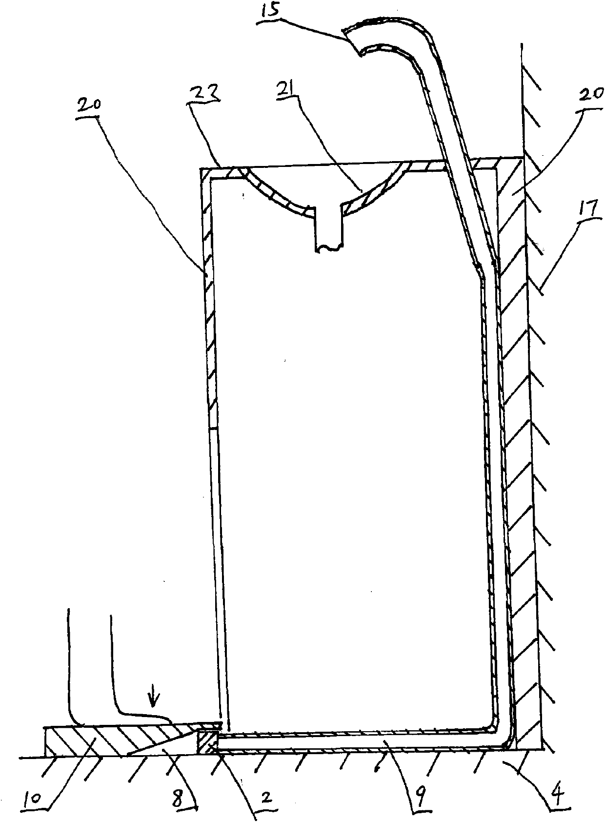
[0009] Embodiment one. The system of the present invention is a liquid control system for liquid input pipelines, especially faucet installations. The system is composed of the mind control device, the water valve body [2] and the system body integrally or in combination. The idea control device is the front and rear end pedal type foot control device, and the front and rear end pedal type foot control device is mainly composed of stepping on the pressing plate [10]. Step on the pressing plate [10], wherein the section position is provided with a rotating shaft or the middle section position can constitute the rotating shaft, which can be roughly divided into two parts of the rotating shaft front end pedal [7] and the rotating shaft rear end pedal [11] by the rotating shaft. Step on the pressing plate [10], the middle section is provided with a rotating shaft, which is a fixed rotating shaft [12] arranged between the base [3] or the ground [4] or other supporting facilities. ...
Embodiment 2
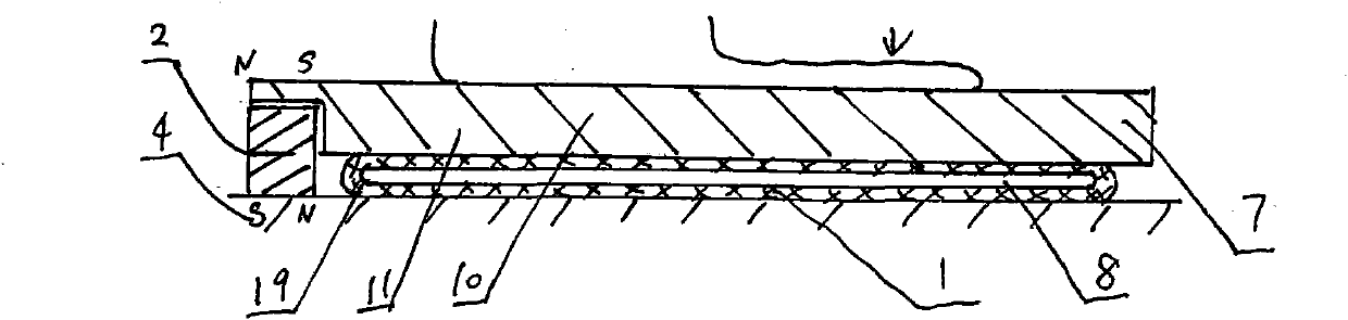
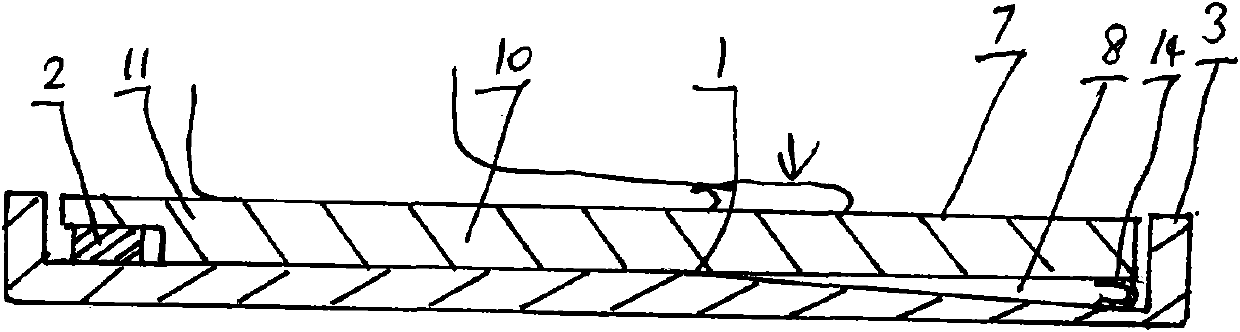
[0013] Embodiment 2, in this example, relative to the movable rotating shaft [1], the treadle at the front end of the rotating shaft [ 7] Partly constitutes the void. Void is set on the treadplate [10] (e.g. figure 1 As shown in stepping on plate [10] middle section begins to grind forward or dig out a section of inclined surface or parallel surface part). Or the void is set on the base [3] or the ground [4] or other supporting facilities (such as image 3 Grinding or digging out a section of inclined surface or parallel surface part on the base [3] or the ground [4] or other supporting facilities as shown). Perhaps the void is to step on the pressing plate [10] and the base [3] or the ground [4] or other supporting facilities at the same time and each set a part (such as Figure 4 Show, while stepping on the plate [10] and base [3] or ground [4] or other supporting facilities to grind or dig out a section of inclined surface or parallel surface part).
Embodiment 3
[0014] Embodiment three, the fixed rotating shaft [12] of this example is a solid rotating shaft [18] formed between the middle part of the pressing plate [10] and the base [3] or the ground [4] or other supporting facilities. ](E.g Figure 5 shown). Or be set raised position [5] by stepping on plate [10] midsection position (for example Image 6 shown), form a fixed rotating shaft [12] with the base [3] set or with the ground [4] or with other supporting facilities. Or by the base [3] that is set or with the ground [4] or other supporting facilities, a raised position [5] is set, and cooperates with the middle part of the stepping plate [10] to form a fixed rotating shaft [12].
PUM
 Abstract
Description
Claims
Application Information
 - R&D
- Intellectual Property
- Life Sciences
- Materials
- Tech Scout
- Unparalleled Data Quality
- Higher Quality Content
- 60% Fewer Hallucinations
Browse by: Latest US Patents, China's latest patents, Technical Efficacy Thesaurus, Application Domain, Technology Topic, Popular Technical Reports.
© 2025 PatSnap. All rights reserved.Legal|Privacy policy|Modern Slavery Act Transparency Statement|Sitemap|About US| Contact US: help@patsnap.com