Water saving plug
A water-saving cock and water cylinder technology, which is applied in water supply devices, water resource protection, mixers, etc., can solve problems such as poor user experience and ineffective water-saving effects
- Summary
- Abstract
- Description
- Claims
- Application Information
AI Technical Summary
Problems solved by technology
Method used
Image

Examples
Embodiment 1
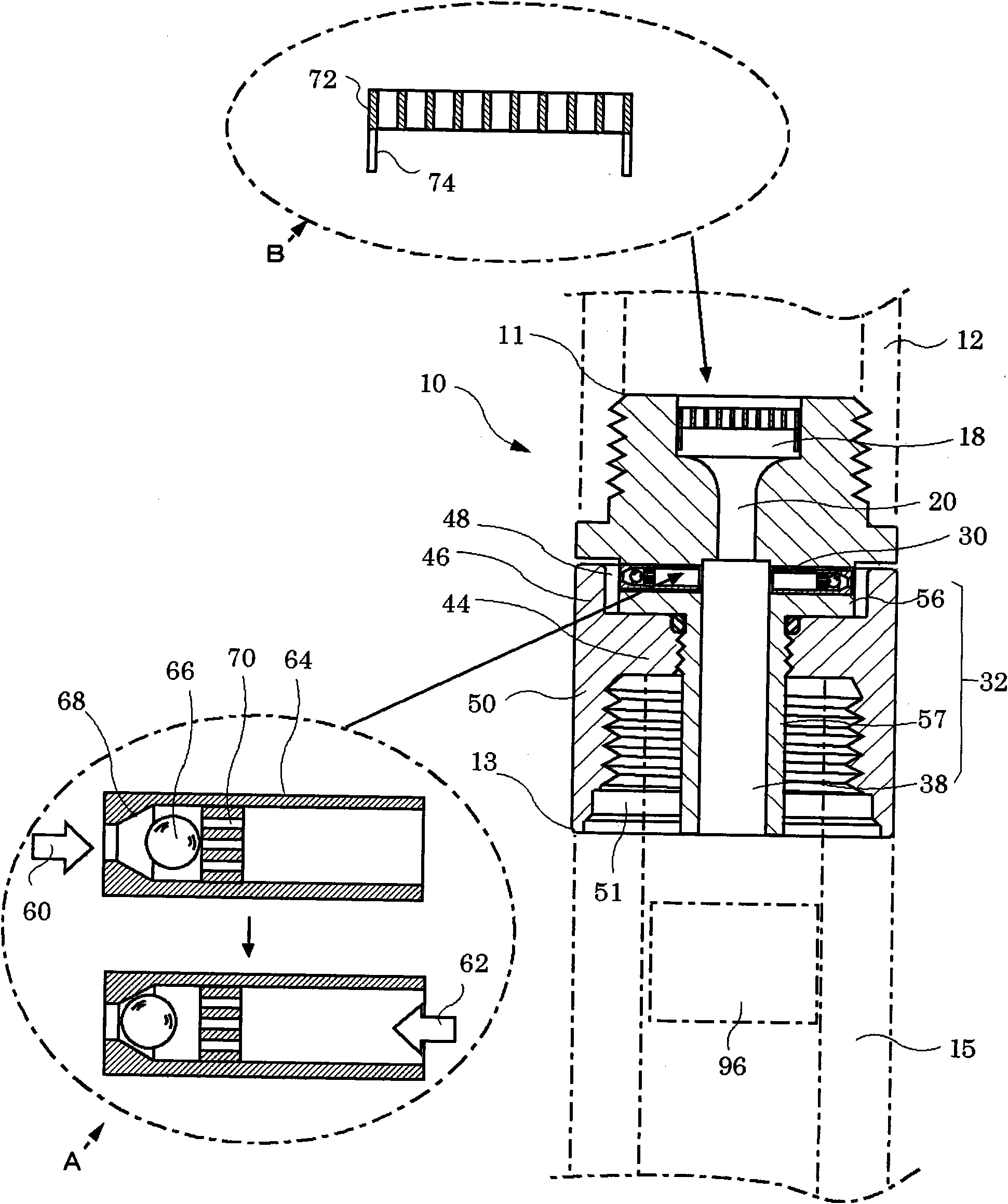
[0106] figure 1 Shown is a longitudinal sectional view of the water-saving hydrant of Example 1.
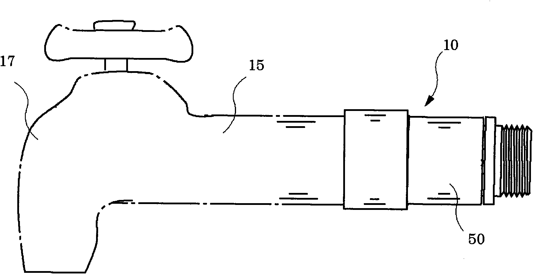
[0107] When installing this water-saving cock 10, it is inserted into the middle of flexible pipe or running water pipe. Shown in the figure is a water saving plug 10 , a tap water pipe 12 is connected to its upstream end 11 , and a pipe 15 is connected to its downstream end 13 . The water pipe 15 is a hose of a shower or a pipe of a water tap. For example, a shower head 16 is connected to the downstream side of the pipe 15 . In addition, it may also be connected to the kitchen tap 17 . The water-saving hydrant 10 utilizes figure 1 For the cross-sectional structure shown, air bubbles were added to tap water. At the same time, the flow rate of the water is increased, thereby increasing the impact force when the water touches the user's hand or skin. Therefore, even if the amount of water is reduced, the feeling of use will not be changed. Therefore, water bills can be sav...
Embodiment 2
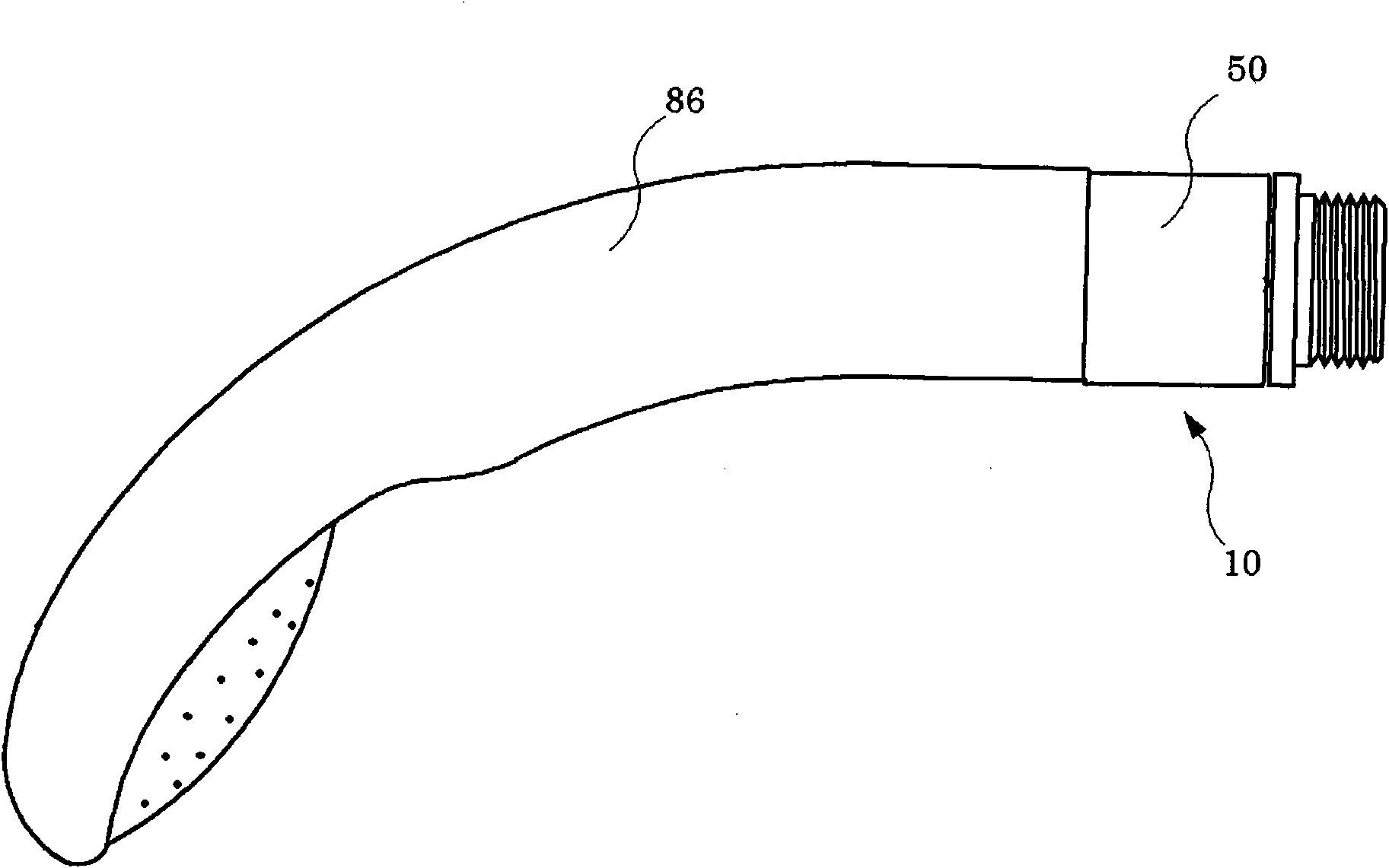
[0128] Figure 10 Shown is the water-saving hydrant of Example 2, (a) is a perspective view of the orifice unit 86, and (b) to (d) are longitudinal sectional views of various modifications of the orifice unit 86 , (e) shows a longitudinal sectional view of the state where the orifice unit 86 is installed in the water-saving cock of Embodiment 1, and (f) shows that the water-saving cock of Embodiment 1 is partially deformed and the section is installed. A longitudinal sectional view of the state of the orifice unit 86 . In addition, only one air suction port 30 is provided in this example. The air suction ports 30 only need to be provided with the necessary number.
[0129] In this embodiment, the orifice portion 20 ( figure 1 ), instead adopting a unit structure that is separated from other parts. The orifice unit 86 is detachably fitted into the water receiving cylinder portion 18 of the faucet. Such as Figure 10 As shown in (a) and (b), the orifice unit 86 is formed ...
Embodiment 3
[0135] Figure 11 Shown is the one-way valve installed in the water-saving hydrant of Example 3, (a) shows a longitudinal sectional view of the one-way valve, and (b) shows an exploded oblique view thereof.
[0136] The one-way valve 64 is inserted into the water-saving plug ( figure 1 ) inside of the air intake port 30. It is a cylindrical body with a tapered hole 68 at one end and accommodates a ball 66 and a stopper 70 embedded therein. One end of the tapered hole 68 has an inner diameter larger in diameter than the ball 66 , and the other end has an inner diameter smaller in diameter than the tapered hole 68 . Thus, when the ball 66 is pushed against the inner surface of the tapered hole 68, it will block the side of the tapered hole 68 of the one-way valve 64. The stopper 70 is a plate for preventing the ball 66 from falling out, and has a plurality of through holes through which air or water can pass.
[0137] Adopt the one-way valve 64 of this structure, allow air ...
PUM
 Abstract
Description
Claims
Application Information
 - R&D
- Intellectual Property
- Life Sciences
- Materials
- Tech Scout
- Unparalleled Data Quality
- Higher Quality Content
- 60% Fewer Hallucinations
Browse by: Latest US Patents, China's latest patents, Technical Efficacy Thesaurus, Application Domain, Technology Topic, Popular Technical Reports.
© 2025 PatSnap. All rights reserved.Legal|Privacy policy|Modern Slavery Act Transparency Statement|Sitemap|About US| Contact US: help@patsnap.com