A combined river gate and water control method thereof

A gate and river technology, which is applied in the field of combined gates and water control of rivers, can solve the problems of unsatisfactory water control effect and poor structural stability, and achieve the effect of improving the safety of the gate and improving the sealing performance of the gate.

Active Publication Date: 2021-02-02
ANHUI UNIVERSITY OF ARCHITECTURE +3
View PDF5 Cites 0 Cited by
  • Summary
  • Abstract
  • Description
  • Claims
  • Application Information

AI Technical Summary

Problems solved by technology

[0005] The purpose of the present invention is to provide a combined river gate and its water control method in order to solve the technical problems of poor structural stability and unsatisfactory water control effect

Method used


Image

  • A combined river gate and water control method thereof
  • A combined river gate and water control method thereof
  • A combined river gate and water control method thereof

Examples


Embodiment 1

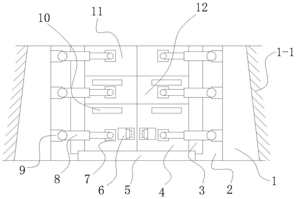
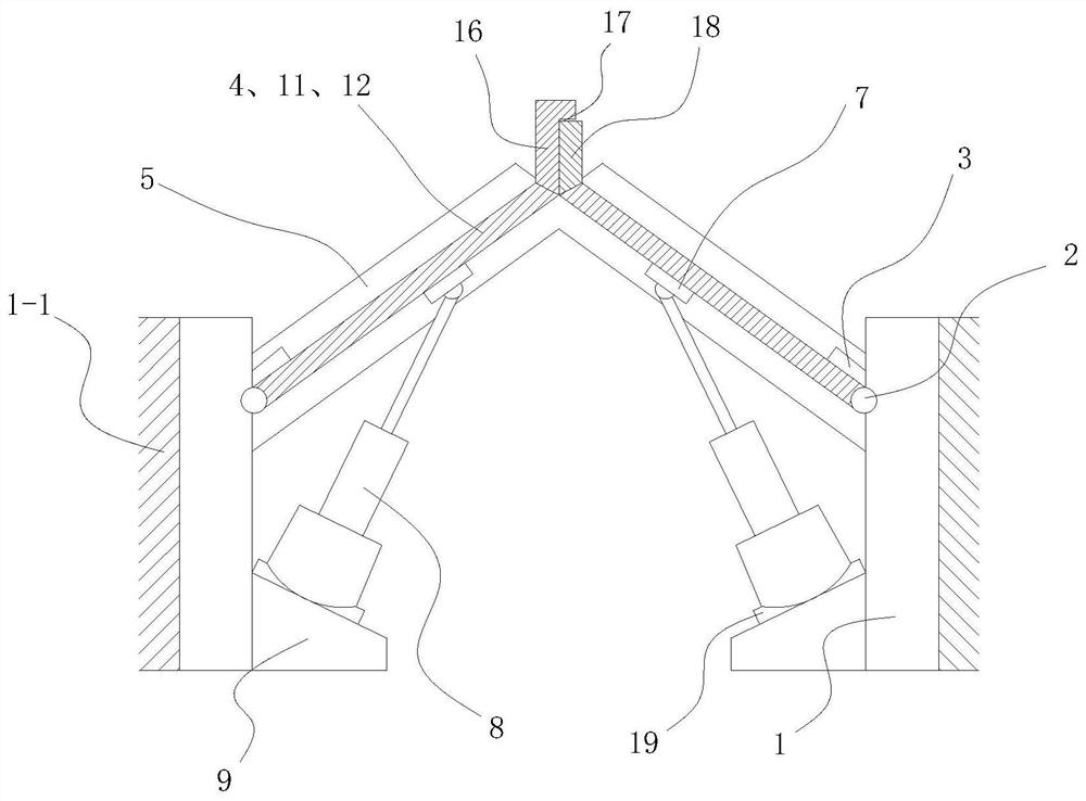
[0045] Embodiment one, with reference to Figure 1-8 , a combination river gate, comprising water retaining walls 1 arranged on both sides of the river, the river retaining wall 1 is a reinforced concrete wall arranged on the inner side of the river embankment 1-1, and vertical Multiple rows of herringbone gate mechanisms with structural self-locking function are arranged side by side; the herringbone gate mechanism includes two left and right gate plates, and the adjacent side ends of the two gate plates are provided with abutment mother board 16 and abutment sub-board 18 The two gate plates are herringbone arranged between the two retaining walls 1, the abutment mother board 16 and the abutment sub-board 18 form a herringbone vertex and face the upstream of the river, the abutment mother board 16 corresponds to the abutment sub-board The board 18 is provided with an abutment groove 17, and the abutment sub-board 18 is occluded and embedded in the abutment groove 17 of the ab...

Embodiment 2

[0057] Embodiment two, refer to Figures 9 to 11 , this embodiment adds the following technical features on the basis of Embodiment 1:

[0058] Also includes an additional locking mechanism 15, the additional locking mechanism 15 is a cable chain type limit mechanism connected with the gate plate; the cable chain type limit mechanism includes a roller frame 152, and the roller frame 152 is fixedly installed on the corresponding side gate On the water retaining wall 1 downstream of the plate, a locking roller 151 is installed on the roller frame 152, and a fixed ring 13 is arranged on the top of the gate plate near the downstream side, and the locking roller 151 is fixedly wound with a cable chain 14, and the outer end of the cable chain 14 is Connected with the fixed ring 13, the end of the locking roller 151 is provided with a locking handle 157, and the roller frame 152 is provided with a locking mechanism corresponding to the locking handle 157; the locking mechanism includ...


PUM


Abstract

The invention discloses a combined river channel gate and a water control method thereof. The combined gate includes water retaining walls arranged on both sides of the river channel, and the river channel water retaining wall is a reinforced concrete wall. The invention cleverly arranges a herringbone gate mechanism, wherein The two gate plates are arranged in a herringbone shape, and the adjacent side ends of the two gate plates are provided with abutting mother plates and abutting sub-plates, which form a herringbone vertex and face upstream of the river; Under the action of the pressure, the structure self-locking is realized, which greatly improves the safety of the gate. In addition, the abutment mother board and the abutment sub-board forming the herringbone vertex are in contact with each other, and an elastic stop is arranged between the abutment mother board and the abutment sub-board. The water rubber pad improves the sealing performance of the gate, and at the same time, the elastic water-stop rubber pad plays a buffer role in the collision process between the abutting motherboard and the abutting sub-board; meanwhile, the vertical multi-row arrangement of the herringbone gate mechanism facilitates the control of water discharge according to needs Or store water, can form waterfall landscape after opening in addition or water store overflows when overflowing.

Description

technical field [0001] The invention belongs to the technical field of river gates, in particular to a combined river gate and a water control method thereof. Background technique [0002] Construction of low-head hydraulic structures using gates to control flow and regulate water level on river courses and channels. Closing the gate can block flood, keep tide or raise the upstream water level to meet the needs of irrigation, power generation, shipping, aquatic products, environmental protection, industrial and domestic water; opening the gate can vent flood, waterlogging, abandoned water or waste water, or Supply water to downstream channels or channels. In water conservancy projects, sluices are widely used as buildings for water retaining, water discharge or water intake; [0003] Sluices, according to their main tasks, can be divided into: control sluices, water intake sluices, sand flushing sluices, flood diversion sluices, tidal sluices, drainage sluices, etc. Accor...

Claims


Application Information

Patent Timeline
Patent Type & Authority Patents(China)
IPC IPC(8): E02B7/20E02B3/12E02B7/54
CPCE02B3/12E02B7/20E02B7/54
Inventor 姚燕生唐建平汪俊葛张森陈庆波丁琨
Owner ANHUI UNIVERSITY OF ARCHITECTURE
Why Eureka
Try Eureka