Naked-eye auto-stereoscopic display projection system and displayer

A technology of stereoscopic display and projection system, which is applied in stereoscopic photography, instruments, photography, etc., can solve the problem of low resolution of the display screen, and achieve the effect of high-resolution stereoscopic display and large-screen stereoscopic display.

Active Publication Date: 2012-07-11
KONKA GROUP
View PDF5 Cites 9 Cited by
  • Summary
  • Abstract
  • Description
  • Claims
  • Application Information

AI Technical Summary

Problems solved by technology

[0003] The purpose of the embodiments of the present invention is to provide a projection system for autostereoscopic display with glasses, aiming to solve the problem of low resolution of the existing autostereoscopic display with glasses

Method used


Image

  • Naked-eye auto-stereoscopic display projection system and displayer
  • Naked-eye auto-stereoscopic display projection system and displayer
  • Naked-eye auto-stereoscopic display projection system and displayer

Examples


Embodiment 1

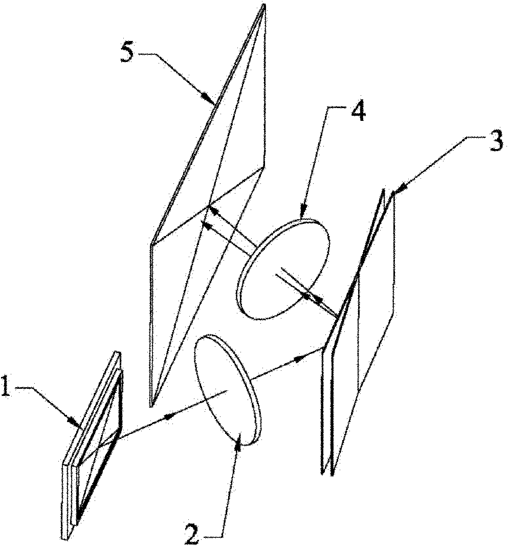
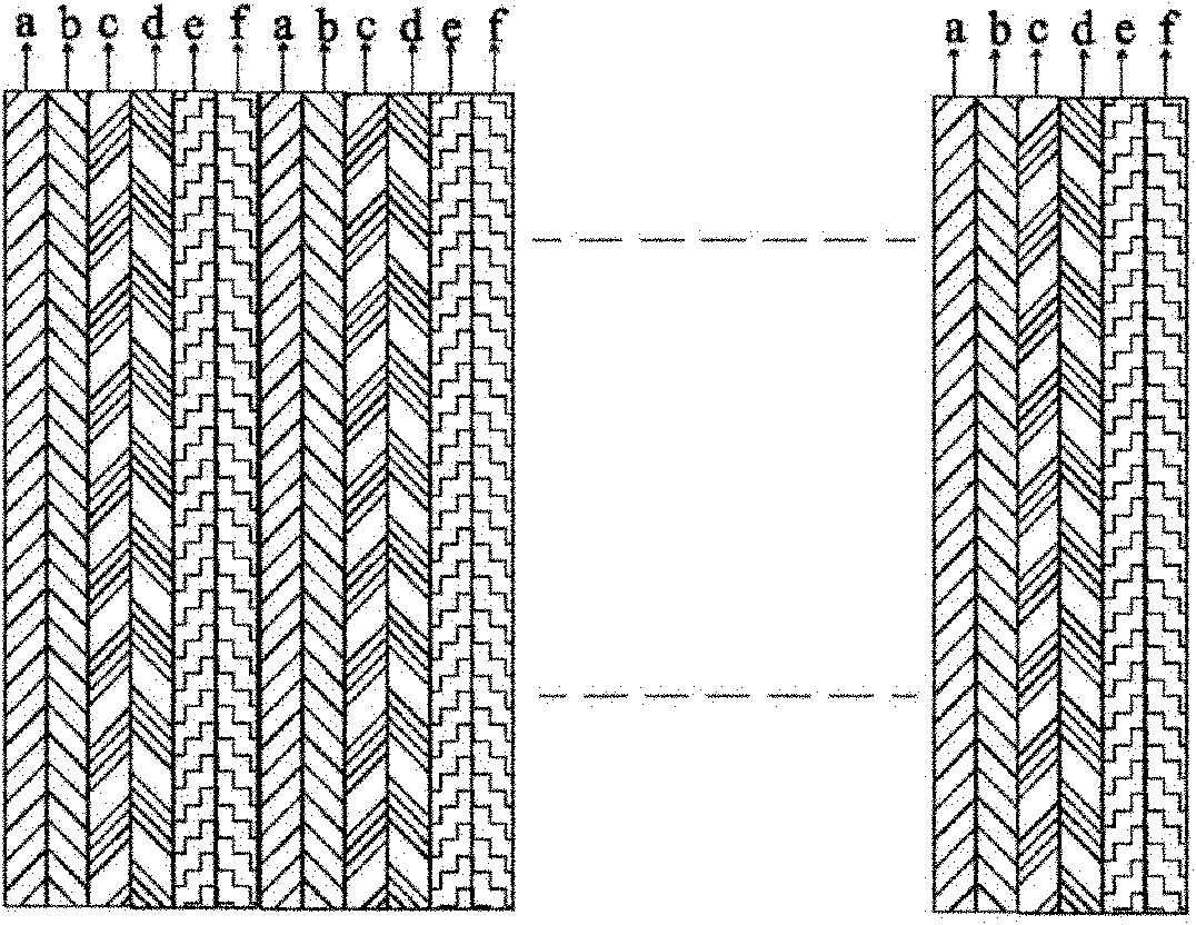
[0034] figure 1 It shows a schematic structural diagram of the naked-eye autostereoscopic display system provided by the first embodiment of the present invention, figure 2 A schematic diagram of multi-viewpoint display and imaging of the display screen provided by the first embodiment of the present invention is shown, and for convenience of description, only parts related to this embodiment are shown.

[0035] The display system includes a micro-display imaging device 1, which modulates incident light (backlight) under the drive of a driving circuit, and converts electrical signals carrying image information into optical image information that can be perceived by human eyes. On the light output direction of the micro-display imaging device 1, a first lens group 2 and a reflector 3 are arranged in sequence, a second lens group 4 is arranged on the reflected light path of the reflector 3, and a second lens group 4 is arranged on the output light path of the second lens group ...

Embodiment 2

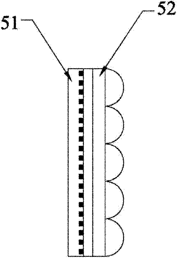
[0040] image 3 A schematic structural diagram of the display screen provided by the second embodiment of the present invention is shown, Figure 4 A display principle diagram of the display screen provided by the second embodiment of the present invention is shown, and for convenience of description, only parts related to this embodiment are shown.

[0041]In the embodiment of the present invention, the display screen 5 may specifically be a composite screen composed of a Fresnel screen 51 and a parallax separation grating 52. The Fresnel screen 51 is a secondary imaging plane, and the parallax separation grating 52 is located on the Fresnel screen. 51 output. The mirror 3 images the sub-image of a certain point of view on the corresponding pixel area of ​​the Fresnel screen 51 through the second lens group 4, and the parallax separation grating 52 transmits the sub-image information to a predetermined point of view, and then transmits the sub-image information of the left e...

Embodiment 3

[0044] In the embodiment of the present invention, the reflective mirror 5 is preferably a high-reflectivity plane mirror with a controllable deflection angle. The deflection angle corresponding to a certain viewpoint can be preset according to the grating pitch.

[0045] In the embodiment of the present invention, at a certain moment, the output image of the micro-display imaging device 1 and the corresponding deflection angle of the mirror 3 can be controlled by a precise control system, and then the images of each viewpoint can be accurately and smoothly transmitted to the The left and right eyes of the human body.

[0046] In the embodiment of the present invention, the micro-display imaging device is used to output the sub-images of each viewpoint in time-sharing, and the sub-images are imaged in the corresponding pixel areas of the display screen by coordinating with the mirror to deflect the corresponding angle, and then the different views are respectively transmitted ...


PUM


Abstract

The invention is suitable for the field of three-dimensional (3D) display and aims to provide a naked-eye auto-stereoscopic display projection system. The naked-eye auto-stereoscopic display projection system comprises a micro-display imaging device. The micro-display imaging device is used for outputting sub-images which correspond to preset viewpoints; the output light path of the micro-display imaging device is provided with a first lens group and a reflecting mirror in sequence; the reflecting light path of the reflecting mirror is provided with a second lens group; the emergent light path of the second lens group is provided with a 3D display screen; the reflecting mirror rotates a corresponding angle, and the sub-images are projected onto the 3D display screen through the second lens group; the sub-images are transmitted to the preset viewpoints by the 3D display screen; the sub-images which correspond to different preset viewpoints are output by the micro-display imaging device in the manner of time sharing, so that different sub-images are respectively transmitted to the left eye and the right eye of an observer by the system according to time sequence to realize auto-stereoscopic display. According to the system, the image synthesis and segmentation process of a traditional 3D display system can be avoided, and the high-resolution stereoscopic display can be directly realized.

Description

technical field [0001] The invention belongs to the field of stereoscopic display, and in particular relates to a projection system and a display for naked-eye free stereoscopic display. Background technique [0002] At present, the stereoscopic display technology mainly includes naked-eye display technology with glasses and without glasses. Although the three-dimensional display mode of wearing glasses is mature in technology, it will bring a lot of inconvenience to people. Naked-eye stereoscopic display will eventually become the goal of stereoscopic display. There are flat-panel display, volumetric stereoscopic display, holographic display, etc. among the imaging methods for realizing naked-eye stereoscopic display. However, the traditional imaging methods need to synthesize several sub-viewpoint pictures into one frame of images, display them on the LCD screen at the same time, and then project the corresponding left and right eye views to the left and right eyes of pe...

Claims


Application Information

Patent Timeline
Patent Type & Authority Applications(China)
IPC IPC(8): G03B35/18G03B21/28G02B27/22
Inventor 王荣王进
Owner KONKA GROUP
Why Eureka
Try Eureka