Eureka AIR delivers breakthrough ideas for toughest innovation challenges, trusted by R&D personnel around the world.

Processing box and image forming device

A technology for processing cartridges and images, which is applied to equipment for electric recording technology using charge patterns, electric recording technology for applying charge patterns, and electrography, etc., and can solve the problem of affecting the positioning accuracy of the processing cartridge 10 and the separation of the processing cartridge 10 from the installation position , high spring performance requirements and other issues, to achieve the effect of increasing stability, reducing requirements, and improving image quality

Active Publication Date: 2012-07-11
ZHUHAI PANTUM ELECTRONICS
View PDF4 Cites 3 Cited by
  • Summary
  • Abstract
  • Description
  • Claims
  • Application Information

AI Technical Summary

Problems solved by technology

The shape design of the guide rail of the existing imaging equipment can only block the vertical component Fny of the radial force Fn of the gear driving force, but cannot effectively block the horizontal component Fnx of the radial force Fn, and it needs to be blocked by elastic pushing parts (such as springs) The cartridge 10 escapes from the guide rail 2, and this position bears a relatively large thrust, which requires high performance of the spring, and affects the positioning accuracy of the process cartridge 10 in the image forming device
Though the cooperation mode of existing image forming equipment and process box 10 is simple, but the photosensitive drum drive gear 15 of process box 10 is subjected to the effect of driving force with image forming equipment main frame drive gear 5 and can make process box 10 break away from installation position, finally result in poor image quality

Method used


Image

  • Processing box and image forming device
  • Processing box and image forming device
  • Processing box and image forming device

Examples


Embodiment Construction

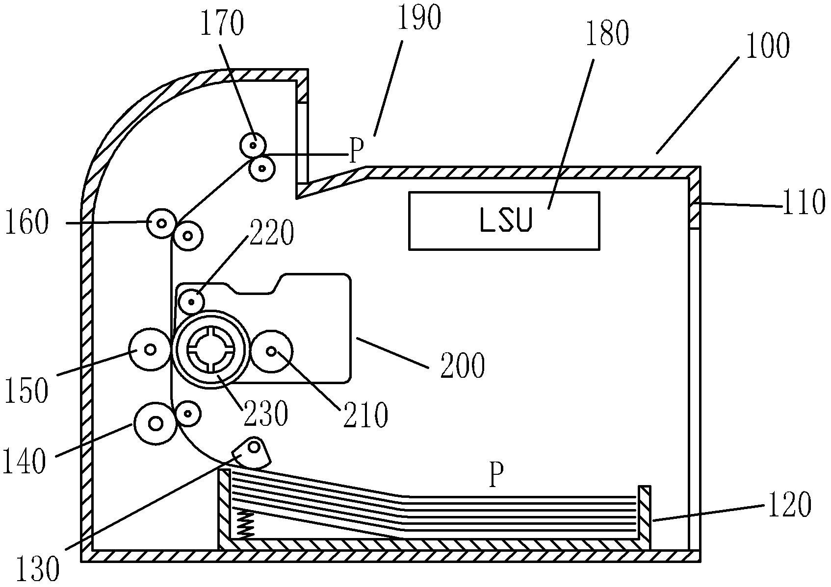
[0033] image 3 A schematic diagram of the structure of the process cartridge installed in the image forming apparatus provided by the embodiment of the present invention. The image forming apparatus may be of any type, such as a printer, a copier, etc., which require a process cartridge to be installed. This embodiment is specifically based on image 3 The typical structure shown is taken as an example for explanation.

[0034] Such as image 3 As shown, the image forming apparatus is a laser printer 100, which includes a main frame 110, a paper supply tray 120 accommodated in the main frame 110 and capable of storing a plurality of printing media P, a paper feeding device 130, a conveying roller 140, a fixing unit 160 , a discharge unit 170 , a transfer roller 150 , and a laser scanning unit (LSU) 180 , and a discharge tray 190 is provided on the upper surface of the main frame 110 . The process box 200 is detachably installed in the laser printer 100 , and the process b...


PUM


Abstract

The invention provides a processing box and an image forming device. The image forming device comprises a main frame; a guide rail is formed in the main frame, a spacing groove is provided at the central part of the guide rail close to the inner side of the image forming device, and the width of the spacing groove is less than the width of the guide rail. The processing box is detachably installed in the image forming device and comprises a photosensitive drum and a first protrusion and a second protrusion extending out from a side face, wherein, the first protrusion is coaxially arranged with the photosensitive drum along the installation direction of the processing box, the second protrusion is located at the upper steam of the first protrusion, and the length of the second protrusion is less than that of the first protrusion. According to the invention, by arranging the guide rail at the central part of the guide rail, better spacing of the processing box in the image formation device is realized, and the processing box can be more firmly installed and be installed and dismantled smoothly.

Description

technical field [0001] The present invention relates to mechanical structure technology, and in particular to a process cartridge and an image forming apparatus. Background technique [0002] At present, with the advancement of science and technology, image forming equipment such as laser printers, copiers, fax machines, and multifunctional machines are widely used in people's work and life. [0003] A laser printer as a typical image forming device has an imaging principle as follows: a laser performs selective exposure on a photosensitive member uniformly charged by a charging device in a process cartridge according to image information to form a corresponding electrostatic latent image. The latent image on the photosensitive member is then developed to form a toner image, and the toner image on the photosensitive member is transferred to a printing medium by a transfer device, thereby forming a visible toner image on the printing medium. The process cartridge integrates ...

Claims


Application Information

Patent Timeline
Patent Type & Authority Applications(China)
IPC IPC(8): G03G15/00G03G21/18
Inventor 夏巨政葛岳超李荣华
Owner ZHUHAI PANTUM ELECTRONICS
Why Eureka
Eureka Blog
Learn More