Electric connector shielding structure and producing method

A technology of electrical connectors and shielding structures, which is applied in the direction of connecting parts, protective grounding/shielding devices, connections, line/collector parts, etc., which can solve the problems of shortening the service life of cover plates, fewer types of conductive plastics, and affecting shielding effects, etc. , to reduce weight, high processing efficiency and small volume

Active Publication Date: 2015-03-18
SICHUAN HUAFENG ENTERPRISE GRP
View PDF11 Cites 0 Cited by
  • Summary
  • Abstract
  • Description
  • Claims
  • Application Information

AI Technical Summary

Problems solved by technology

The disadvantages of this plastic shielding cover are: (1) There are few conductive plastics available in the market, and they are expensive, resulting in increased costs; (2) Due to the internal stress in the injection molding process, the existence of internal stress It may deform or even crack the injection molded parts during use, which not only shortens the service life of the cover plate, but also seriously affects the shielding effect

Method used


Image

  • Electric connector shielding structure and producing method
  • Electric connector shielding structure and producing method

Examples


Embodiment Construction

[0021] The present invention will be described in detail below in conjunction with the accompanying drawings and embodiments, but they are not further limitations on the present invention.

[0022] The shielding structure and manufacturing method of the electrical connector provided by the present invention are applicable to various electrical connectors for transmitting signals.

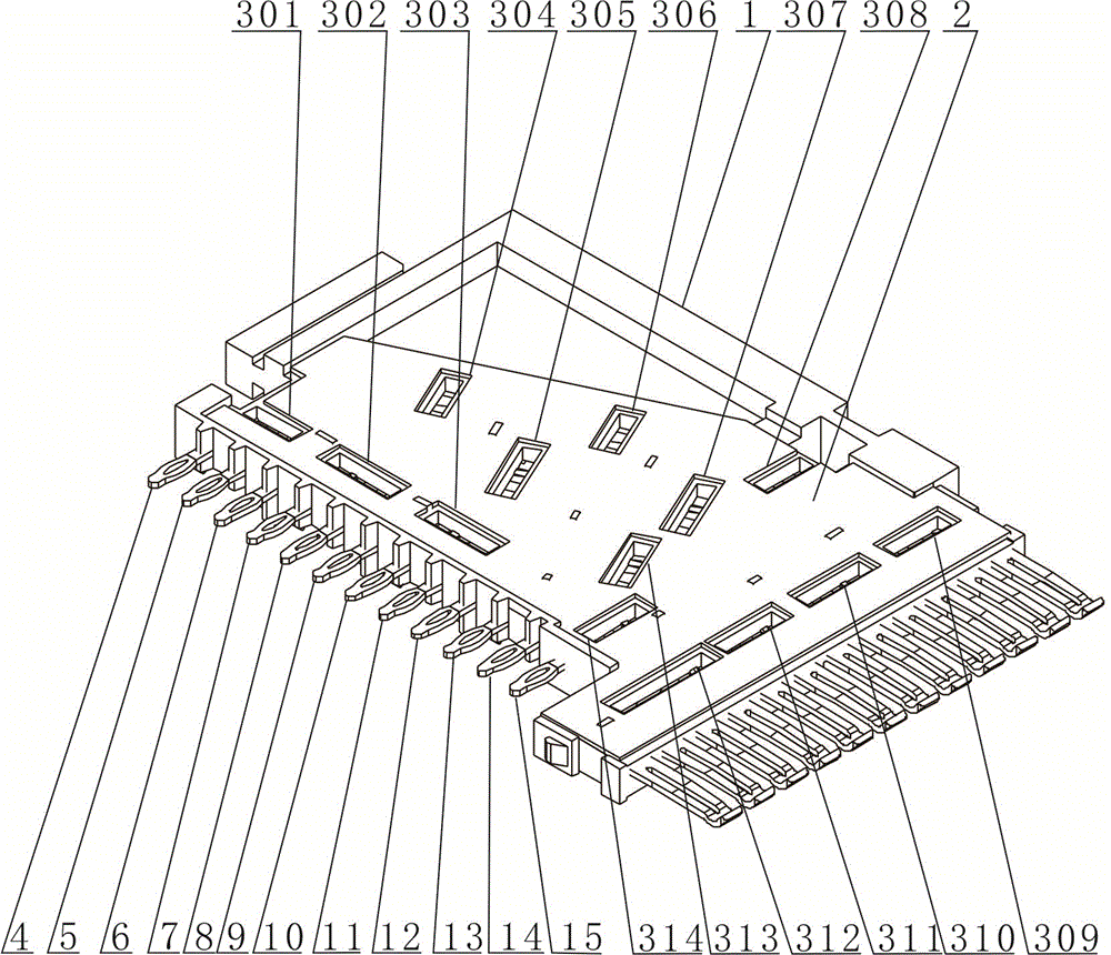
[0023] This embodiment takes figure 1 The illustrated electrical connector is taken as an example to describe the shielding structure provided by the present invention in detail.

[0024] Such as figure 1 As shown, the electrical connector includes a contact, a plastic base 1 disposed outside the contact, and an electroplating layer 2 disposed on the outer surface of the plastic base 1 .

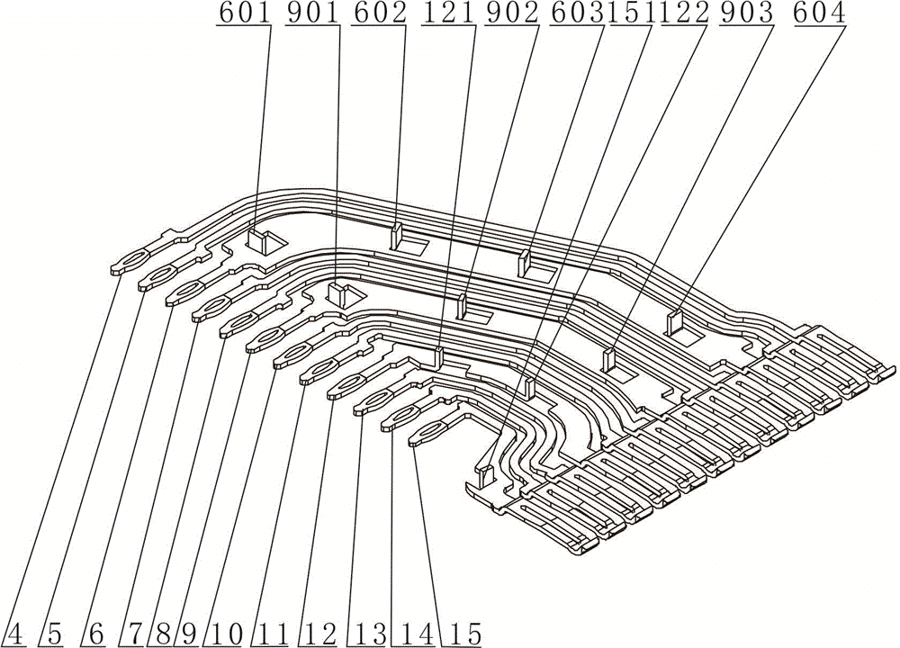
[0025] Such as figure 2 As shown, the contacts of the electrical connector include signal contact a4, signal contact b5, ground contact a6, signal contact c7, signal contact d8, ground contact b9, signal conta...


PUM


Abstract

The invention discloses an electric connector shielding structure. The electric connector comprises a contact element, wherein the contact element comprises a signal contact element and an earthing contact element; multiple extension parts are arranged on the earthing contact element; a plastic matrix is arranged outside the contact element; an electroplated layer is arranged on the external surface of the plastic matrix; openings matched with the extension parts arranged on the earthing contact element are arranged on the plastic matrix; the extension direction of the extension parts arranged on the earthing contact element is the thickness direction of the earthing contact element; the electroplated layer is electrically connected with the extension parts arranged on the earthing contact element; and the extension parts arranged on the earthing contact element extend out of the external surface of the plastic matrix. The electric connector shielding structure is produced by injection molding and electroplating processes. By adopting the electric connector shielding structure, the multipoint connection between the earthing contact element and the electroplated layer of the electric connector is realized, thus the shielding is sufficient, and the crosstalk among signal wires in the electric connector is low; and the plastic matrix is not limited by the material, thus the cost and connector weight are greatly reduced.

Description

technical field [0001] The invention belongs to the technical field of electric connector structure and manufacture, and in particular relates to a shielding structure and a manufacturing method of an electric connector. Background technique [0002] In the field of communication, there are more and more applications of communication equipment for signal transmission, especially electrical connectors with high transmission speed. In order to meet the high transmission rate, the crosstalk requirements of the electrical connectors in the transmission link should be as small as possible, and the electrical connectors with low crosstalk characteristics play an important role in high-speed signal transmission. In the field of high-speed connectors, there are two main ways to achieve low crosstalk: (1) The signal lines are close to each other to form strong coupling, which in turn has strong anti-interference; (2) Make the ground wire and shield of the contact component fully con...

Claims


Application Information

Patent Timeline
Patent Type & Authority Patents(China)
IPC IPC(8): H01R13/648H01R13/46H01R43/00
Inventor 陈学军何洪张洺诚
Owner SICHUAN HUAFENG ENTERPRISE GRP
Why Eureka
Try Eureka