Busbar-free high-efficiency back-contact solar cell, module and its preparation process

A technology for solar cells and solar cells, applied in the field of solar cells, can solve the problems of inability to realize, corrode, increase in series resistance, etc., and achieve the effects of reducing the difficulty of series connection, reducing the transmission distance, and reducing the series resistance

Active Publication Date: 2017-08-08
JOLYWOOD SUZHOU SUNWATT
View PDF6 Cites 0 Cited by
  • Summary
  • Abstract
  • Description
  • Claims
  • Application Information

AI Technical Summary

Problems solved by technology

This process has the following defects: 1. The composite conductive backplane used is a composite conductive metal foil in the backplane, usually copper foil, and the copper foil needs to be laser etched or chemically etched
Since laser etching is still operable for simple patterns, the etching speed is slow and the production efficiency is low for complex patterns, while chemical etching requires pre-prepared complex-shaped and corrosion-resistant masks, environmental pollution and corrosive liquids on polymers. Substrate corrosion problems
Therefore, the manufacturing process of the conductive backplane manufactured in this way is complicated and the cost is extremely high.
2. It is necessary to punch the packaging material of the back layer of the solar cell so that the conductive adhesive can penetrate the packaging material. Since the packaging material is usually a viscoelastic body, it is extremely difficult to accurately punch holes
3. Accurate dispensing equipment is required to coat the conductive glue on the corresponding position of the back plate. It can also be operated for batteries with fewer back contacts such as MWT, and for back contact batteries with small and large number of back contacts such as IBC. Simply not possible with dispensing equipment
[0012] To sum up, using thin grid lines for current collection will encounter problems such as increased series resistance and decreased fill factor, resulting in a serious reduction in the power of the manufactured components; screen printing wider silver paste grid lines to reduce series resistance , but the cost will rise sharply due to the increase in the amount of silver used, and at the same time, the wide gate line will also cause the insulation effect between P-N to deteriorate, and the problem of easy leakage
If metal conductive wires are used to collect the conductive particles of the back-contact solar cells, since the thickness of ordinary solar cells is only 180 microns, in order to accurately position, when welding metal conductive wires, it is generally necessary to apply a tension before welding. Will be subject to the longitudinal stress of the conductive wire, easy to bend
And if the entire string of solar cells is strung together using the same conductive wire, it will increase the difficulty of series connection and the probability of "wrong connection", and hinder the thin development of solar cells (the theoretical thickness of solar cells is 45 microns can)

Method used


Image

  • Busbar-free high-efficiency back-contact solar cell, module and its preparation process
  • Busbar-free high-efficiency back-contact solar cell, module and its preparation process
  • Busbar-free high-efficiency back-contact solar cell, module and its preparation process

Examples


Embodiment 1

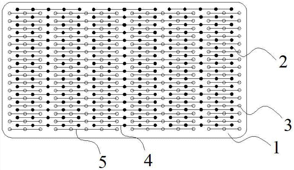
[0066] refer to figure 1 , figure 2 and Figure 4 , a busbar-free high-efficiency back-contact solar cell, the solar cell includes a solar cell sheet 1 and an electrical connection layer, the backlight surface of the solar cell sheet 1 has a P electrode connected to a P-type doped layer and an N-type doped layer The N electrode connected by heterogeneous layers is characterized in that: the electrical connection layer includes several conductive thin grid lines, and a part of the conductive thin grid lines is connected to the P electrode on the backlight surface of the solar battery sheet 1; the other part of the conductive fine grid lines The grid lines are connected to the N electrodes on the backlight surface of the solar battery sheet 1 , and the thin conductive grid lines have a multi-segment structure.

[0067] Such as Figure 4 Shown is a busbar-free high-efficiency back-contact solar battery sheet-8, in which there are 15 rows of dot-shaped P electrodes 2, 16 in ea...

Embodiment 2

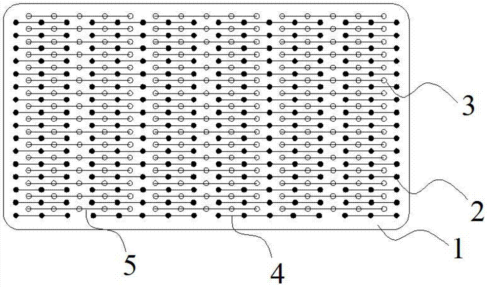
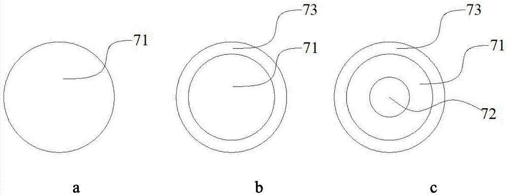
[0089] refer to Figure 5 , Figure 6 and Figure 7 , a busbar-free high-efficiency back-contact solar cell, the solar cell includes an electrical connection layer composed of more than one solar cell sheet 1, conductive wires 7 and conductive thin grid lines, and the silicon substrate backlight surface of the solar cell sheet 1 has The P electrode connected to the P-type doped layer and the N electrode connected to the N-type doped layer, the electrical connection layer on the backlight surface of the solar cell sheet 1 has several conductive thin grid lines connected to the P electrode and connected to the N electrode. A plurality of conductive thin grid lines, the conductive thin grid lines are multi-segment structures, and the intersections of the conductive thin grid lines and the conductive wires 7 are provided with barriers to prevent the electrical conduction between the conductive thin grid lines and the conductive wires 7. Insulation medium6.

[0090] like Figur...


PUM


Abstract

The invention relates to the field of solar cells, in particular to high-efficiency back-contact solar cells without busbars, components and a preparation process thereof. A busbar-free high-efficiency back-contact solar cell, the solar cell includes a solar cell sheet and an electrical connection layer, and the backlight surface of the solar cell sheet has a P electrode connected to the P-type doped layer and an N electrode connected to the N-type doped layer. The electrode is characterized in that: the electrical connection layer includes several conductive thin grid lines, a part of the conductive thin grid lines are connected to the P electrode on the backlight surface of the solar cell sheet; the other part of the conductive thin grid lines is connected to the solar cell The N electrode on the backlight surface of the cell is connected, and the conductive thin grid line is a multi-segment structure. The beneficial effect is that the amount of silver paste is reduced and the cost is reduced. The arrangement of multi-segment conductive thin grid lines reduces the series resistance and the transmission distance of the fill factor, improves efficiency, and can effectively reduce the impact of conductive thin grid lines on the battery sheet. stress.

Description

technical field [0001] The invention relates to the field of solar cells, in particular to high-efficiency back-contact solar cells without busbars, components and a preparation process thereof. Background technique [0002] Energy is the material basis of human activities. With the continuous development and progress of human society, the demand for energy is increasing day by day. Traditional fossil energy is non-renewable energy and it is difficult to continue to meet the needs of social development. Therefore, research and utilization of new energy and renewable sources have become increasingly popular in countries around the world in recent years. Among them, solar power generation technology has the advantages of directly converting sunlight into electricity, simple use, environmental protection and pollution-free, high energy utilization rate, etc., and has received widespread attention. Solar power generation uses large-area P-N junction diodes to generate photo-gen...

Claims


Application Information

Patent Timeline
Patent Type & Authority Patents(China)
IPC IPC(8): H01L31/0224H01L31/048H01L31/18
CPCH01L31/0224H01L31/18H01L31/048H01L31/0682H01L31/1804Y02E10/547H01L31/0201H01L31/022441H01L31/0512H01L31/0516Y02P70/50H01L31/02002H01L31/022466H01L31/0504H01L31/186
Inventor 林建伟夏文进孙玉海张育政
Owner JOLYWOOD SUZHOU SUNWATT
Why Eureka
Try Eureka