Supercharge Your Innovation With Domain-Expert AI Agents!

Transmission between an engine input shaft and an output shaft of a motor vehicle

A technology for output shafts and transmissions, applied in the direction of mechanical drive clutches, agricultural machinery and implements, mechanical equipment, etc., can solve the problems of lack of reliability, complicated second clutch control device, etc., and achieve the effect of completely reliable operation

Active Publication Date: 2014-12-03
FRANCE REDUCTEURS SA
View PDF5 Cites 0 Cited by
  • Summary
  • Abstract
  • Description
  • Claims
  • Application Information

AI Technical Summary

Problems solved by technology

[0004] However, until now, the second clutch control has been made in a complex and unreliable manner

Method used


Image

  • Transmission between an engine input shaft and an output shaft of a motor vehicle
  • Transmission between an engine input shaft and an output shaft of a motor vehicle
  • Transmission between an engine input shaft and an output shaft of a motor vehicle

Examples


Embodiment Construction

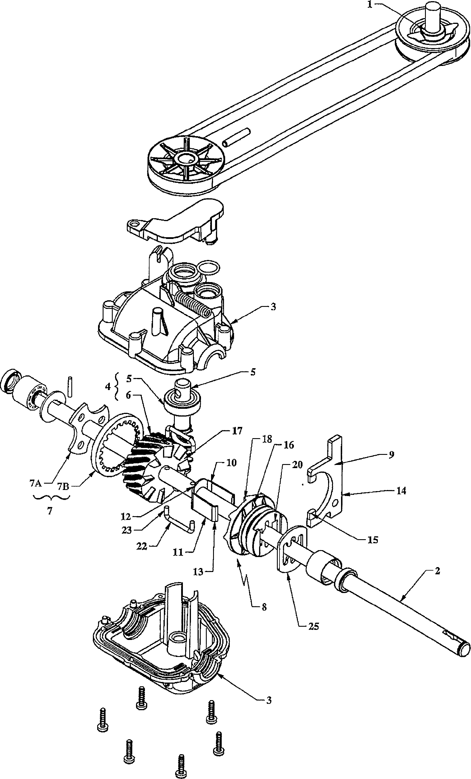
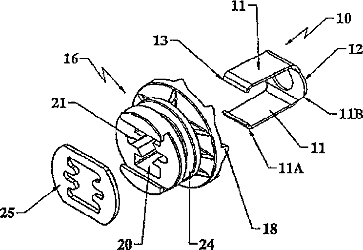
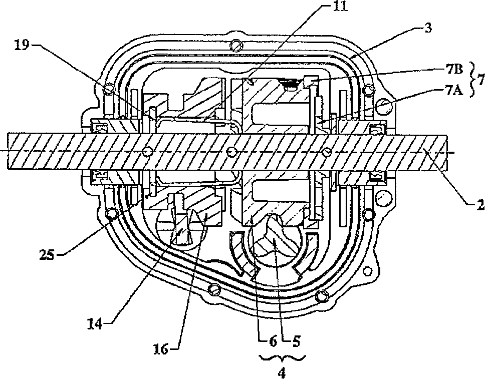
[0023] As described above, the transmission of the present invention is used to transmit rotational motion from a drive shaft 1 of a self-propelled machine, such as a lawnmower, to an output shaft 2, such as a shaft for driving the wheels of the machine, and comprises at least one A housing 3 , which is usually made of synthetic material, comprises, for example, two half-shells, which are assembled together via a joint surface. The housing 3 at least partially houses: a reduction mechanism 4; two clutch mechanisms 7 and 8; and a clutch control device. as in figure 1shown in the reduction mechanism 4 comprises a drive member 5, formed, for example, by a worm, which engages with a driven rotating member 6, which in the example shown is free to rotate by being mounted on the output shaft 2 And free axially moving gears are formed. The driven rotating member 6 or gear is adapted to be engaged / disengaged from the output shaft 2 by means of two clutch mechanisms 7 and 8 , each of ...


PUM


Abstract

A transmission between a driving primary shaft and an outlet shaft of a self-propelled machine, includes a housing within which there are housed, at least in part: a stepdown mechanism; two clutch mechanisms, one being progressive and the other being non-progressive with a movable dog; and a clutch control device including first and second clutch control elements. The second clutch control elements include at least one spring blade extending along the outlet shaft, the spring blade being mounted to move axially on the outlet shaft during axial movement of the dog from the unclutched extreme position towards a clutched position as a result of the movable dog bearing thereagainst, the spring blade being drivable axially on the shaft and being elastically deformable between an active position in which the dog comes into abutment against the spring blade, and an inactive position in which the dog slides along the spring blade.

Description

technical field [0001] The present invention relates to a transmission between a drive shaft of a self-propelled machine and an output shaft such as a wheel drive shaft. Background technique [0002] The invention more particularly relates to a transmission of the type comprising at least one housing within which is at least partially housed a reduction mechanism comprising a drive member such as a worm, the drive member being connected to a gear such as a gear The driven rotating member is engaged, the driven rotating member is freely rotatably mounted on the output shaft; two clutch mechanisms, one of which is progressive and the other is non-progressive with movable pawls, whereby The driven rotating member is adapted to be coupled to / disengaged from the output shaft; and a clutch control device including a first clutch control device and a second clutch control device for driving a non- The movable pawl of the progressive clutch mechanism moves axially along the output ...

Claims


Application Information

Patent Timeline
Patent Type & Authority Patents(China)
IPC IPC(8): A01D34/68F16D23/04F16H63/30
CPCF16D11/14F16D23/04F16H63/30F16H2063/3093A01D34/6812
Inventor 罗伯特·布朗夏尔
Owner FRANCE REDUCTEURS SA
Features
  • R&D
  • Intellectual Property
  • Life Sciences
  • Materials
  • Tech Scout
  • Unparalleled Data Quality
  • Higher Quality Content
  • 60% Fewer Hallucinations
Learn More