Workpiece material and grasping mechanism

A technology for processing materials and holding parts, applied in metal processing, metal processing equipment, mechanical equipment, etc., can solve the problems of reduced tool and device life, increased processing tool load, and increased chip processing burden, etc. The effect of shortening the time and reducing the material removal part

Inactive Publication Date: 2014-11-19
CITIZEN WATCH CO LTD +1
View PDF6 Cites 0 Cited by
  • Summary
  • Abstract
  • Description
  • Claims
  • Application Information

AI Technical Summary

Problems solved by technology

[0007] However, as in the former case, when a long round bar is used as the processing material 500, and the processing material 500 is sequentially sent out by an automatic lathe, and the cutting processing (material removal processing) and cutting processing are repeated, as in Figure 16 As shown, there are many material removal parts 509 that appear due to cutting, the waste of material increases, and the burden on the disposal of discharged chips also increases.
[0008] Moreover, there are many material removal parts 509 due to cutting, so there are problems that the processing time per product becomes longer, the load applied to the processing tool and processing device becomes larger, and the power consumption becomes larger, and the tool , the life of the device will also be reduced
[0013] Therefore, in the case where a plurality of rough materials that are formed into a product through the above-mentioned material removal processing are formed into an integral shape, there is a problem that, for example, an error due to the positional shift needs to be taken into consideration. On the other hand, there are situations in which the effect of reducing the material removal part to reduce the waste of material and reducing the processing burden of discharged chips is limited, and when the error is large, There are cases where there is no machining allowance and it may not be possible to process

Method used


Image

  • Workpiece material and grasping mechanism
  • Workpiece material and grasping mechanism
  • Workpiece material and grasping mechanism

Examples


Embodiment Construction

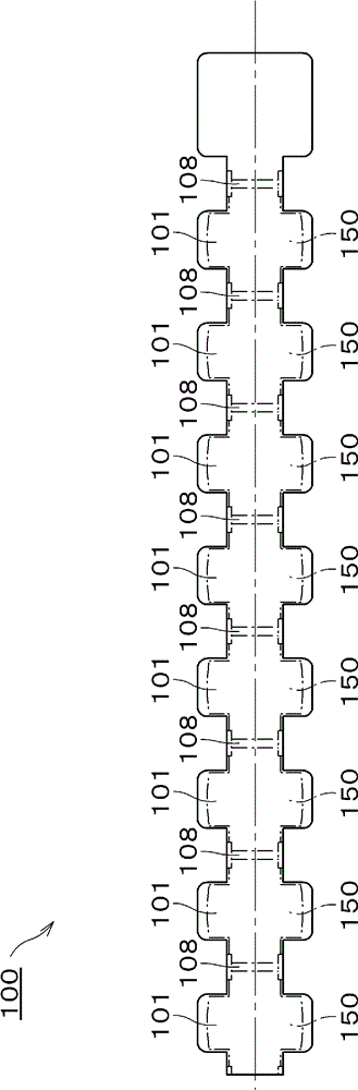
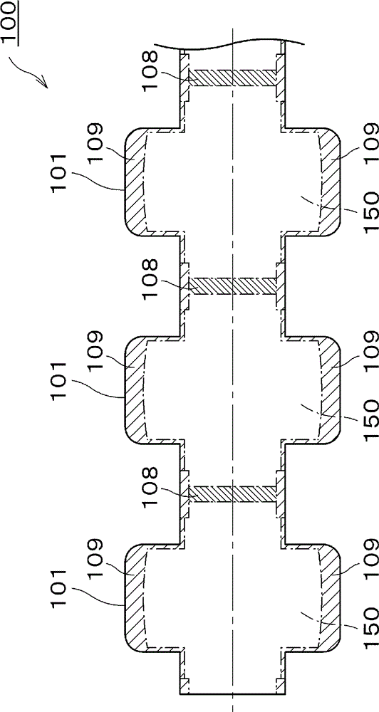
[0066] First, the processed material of the present invention, that is, the processed material 100 of the first embodiment will be described.

[0067] Such as figure 1 , figure 2 As shown, the processed material 100 is configured such that a plurality of rough materials 101 are arranged in a row with a margin for cutting 108 provided therebetween, and are formed integrally from a single material.

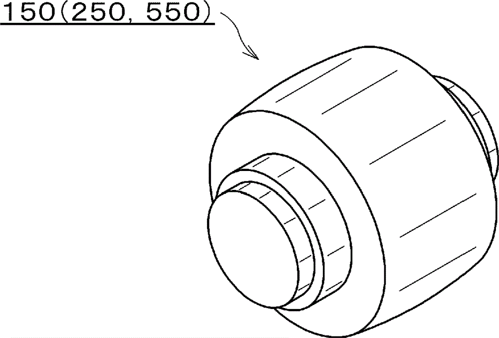
[0068] Each rough material 101 has a required material removal portion 109 on the outer periphery in such a manner that it is formed into one product by material removal processing such as cutting, and presents a shape similar to that of image 3 The product 150 shown is externally similar in shape. In addition, the product may be a semi-finished product that requires secondary processing or the like in addition to a finished product that has been completely processed.

[0069] If the material is a metal material, the processed material 100 may be a material formed integrally by...


PUM


Abstract

There are provided a work material and a gripping mechanism capable of shortening a handling time not involved in works, shortening a time required for producing a plurality of finished members as a whole, accurately positioning the work material even if there is an axial dimension error, lessening waste of a material and lightening a burden for disposing discharged chips. The work material (100) has a shape in which a plurality of raw blanks (101) that become products by material removing works is integrally molded. The gripping mechanism (110) comprises a free moving means (120) that relatively and freely moves a gripper (112) and the work material (100) and a positioning means for defining axial gripping position of the gripper (112) and the work material (100).

Description

technical field [0001] The invention relates to processing materials and a holding mechanism. Background technique [0002] Conventionally, the technology of holding the processing material by a holding mechanism and obtaining a product from the material removal part through material removal processing has been widely used. technology. [0003] For example, the following techniques are known: image 3 In the case of a component as shown as product 550, it will be possible to obtain multiple Figure 16 A long round bar of a product 550 as shown is used as a processing material 500, and is grasped by a gripping mechanism provided on the spindle of an automatic lathe to perform cutting processing (material removal processing) and cutting processing, and the processing material 500 is sequentially sent out and positioned repeatedly. , so that a plurality of products 550 can be continuously obtained by handling the installation processing material 500 . [0004] After each pro...

Claims


Application Information

Patent Timeline
Patent Type & Authority Patents(China)
IPC IPC(8): B23B1/00B23B31/02B29C33/12B29C45/14B29C45/26
CPCB23B2270/16B23B1/00B22C9/22B23B31/16275Y10T279/17042Y10T428/15Y10T428/24612Y10T428/24331Y10T83/04
Inventor 中谷尊一粕谷浩史
Owner CITIZEN WATCH CO LTD
Why Eureka
Try Eureka