Wireless power transmission system and wireless power transmission apparatus
A technology for wireless power and transmission systems, applied in circuit devices, electromagnetic wave systems, near-field transmission systems using transceivers, etc., and can solve problems such as influence
- Summary
- Abstract
- Description
- Claims
- Application Information
AI Technical Summary
Problems solved by technology
Method used
Image

Examples
Embodiment 1
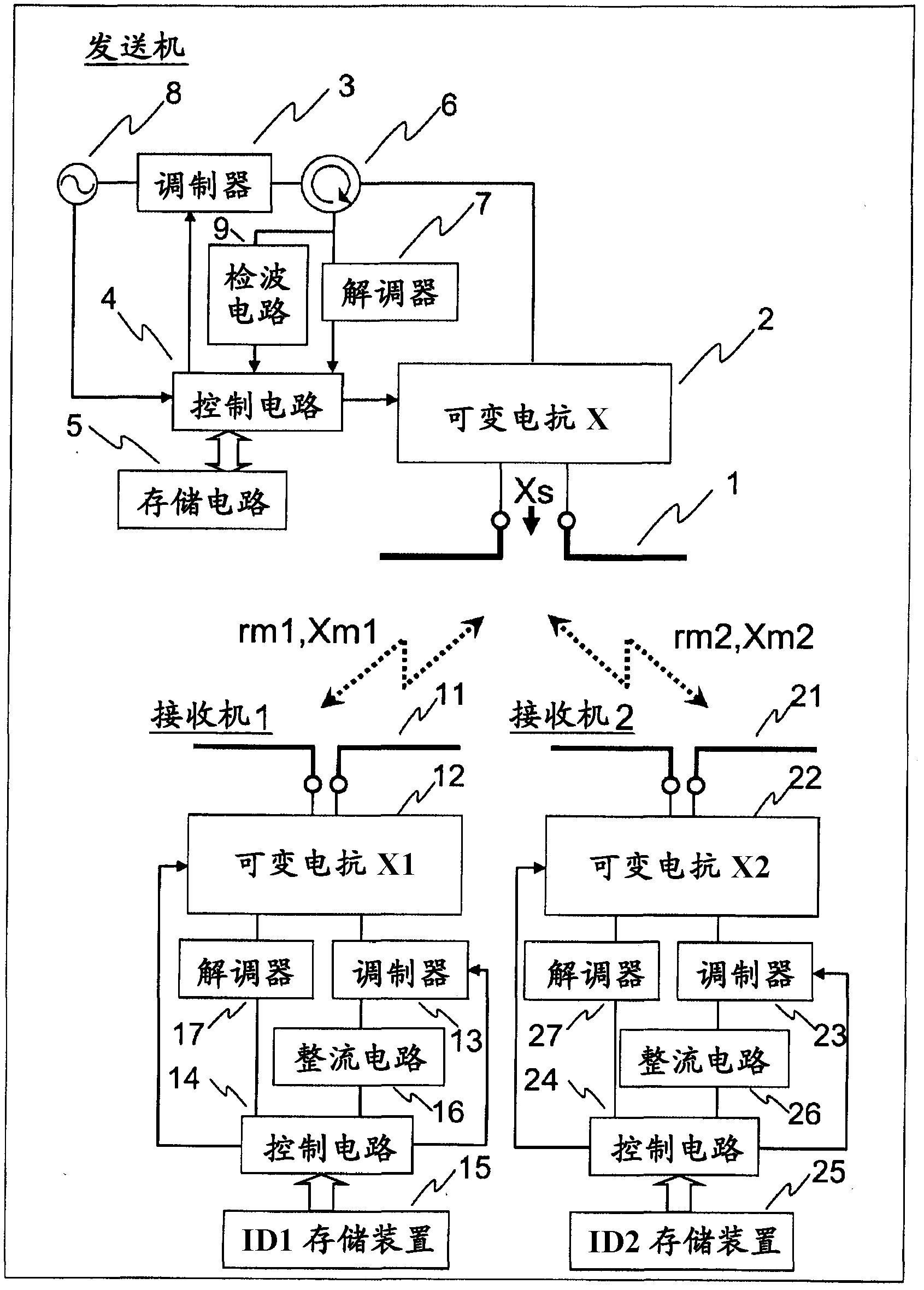
[0063] figure 1 It is a diagram showing the configuration of an embodiment of an ID-controlled one-to-many wireless power transmission system according to the present invention, which is composed of a transmitter and two receivers, that is, a first receiver and a second receiver. The directional coupler 6 of the transmitter is connected to the transmission part variable reactance circuit 2 coupled to the transmission part antenna 1, and the carrier generation circuit 8 of the modulator 3 and the parallel connection of the transmission part demodulator 7 and the detection circuit 9 are interposed. Also connected with this directional coupler 6, the output of this transmitter demodulator 7 and detection circuit 9 is input to transmitter control circuit 4, this transmitter control circuit 4 is connected with storage circuit 5, and is connected with carrier generation circuit 1 The input signal of the transmitter controls the transmitter modulator 3 and the variable reactance circ...
Embodiment 2
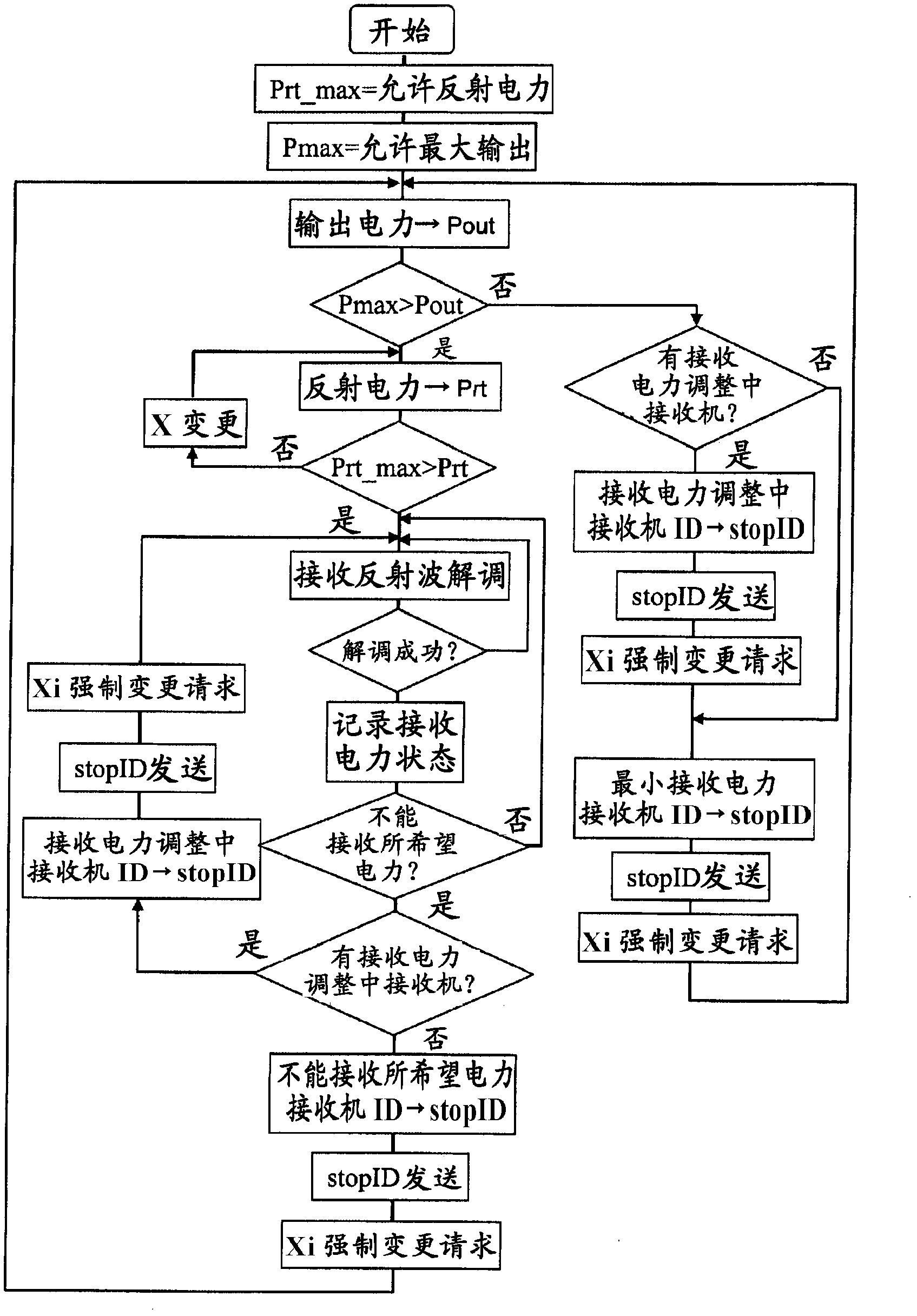
[0066] figure 2 It is a flowchart showing the operation of a transmitter which is a constituent element of an ID control one-to-many wireless power transmission system according to the present invention. Since the transmitter cannot generate unlimited power, the allowable maximum output Pmax is predetermined. Ideally, all the electric power generated from the carrier wave generation circuit 8 is output from the transmitter antenna 1 to the outside space, but actually a part of the power is not output to the outside and returns to the inside of the transmitter. Since high-efficiency power transfer efficiency from the transmitter to the receiver is achieved by reducing this returned power, the maximum allowable value of this returned power is determined in advance as the allowable reflected power Prt_max. In order to keep the output of the carrier generation circuit 8 to a certain limit, a part of the output of the carrier generation circuit 8 is branched and monitored. When ...
Embodiment 3
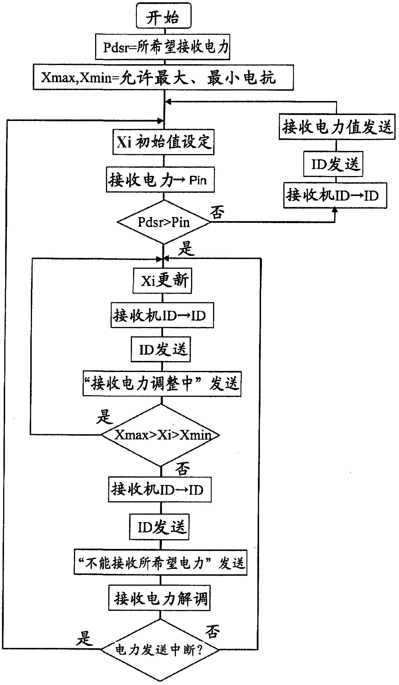
[0070] image 3 It is a flowchart showing the operation of a receiver which is a component of an ID control one-to-many wireless power transmission system according to the present invention. The receiver specifies a preset required power reception amount as the desired reception power Pdsr. Generally, since a receiver is required to be miniaturized, the scale of the variable reactance circuit 12 of the receiving unit cannot be increased, and the variable width of the reactance value is limited by Xmix and Xmax.
[0071] First, the receiver determines the initial reactance value of the receiving unit variable reactance circuit 12, and the receiving unit control circuit 14 monitors the output of the rectifying circuit 16 to obtain the received power at that time. When the received power reaches Pdsr, the ID, the received power value, and the information on power reception are transmitted to the transmitter as they are.
[0072] If the received power does not reach Pdsr, the re...
PUM
 Abstract
Description
Claims
Application Information
 - R&D
- Intellectual Property
- Life Sciences
- Materials
- Tech Scout
- Unparalleled Data Quality
- Higher Quality Content
- 60% Fewer Hallucinations
Browse by: Latest US Patents, China's latest patents, Technical Efficacy Thesaurus, Application Domain, Technology Topic, Popular Technical Reports.
© 2025 PatSnap. All rights reserved.Legal|Privacy policy|Modern Slavery Act Transparency Statement|Sitemap|About US| Contact US: help@patsnap.com