Permanent magnet rotor assembly provided with welded magnet retaining elements

A technology of permanent magnets and rotors, applied in the direction of electrical components, electric components, magnetic circuit rotating parts, etc., can solve the problems of increasing the manufacturing cost of the rotor, high cost, and time-consuming

Inactive Publication Date: 2012-07-11
TM4 INC
View PDF0 Cites 17 Cited by
  • Summary
  • Abstract
  • Description
  • Claims
  • Application Information

AI Technical Summary

Problems solved by technology

Second, the costs associated with using adhesives are quite high when adding the price of the adhesive, labor costs, tooling costs and part cleaning costs
In practice, for the adhesive to work properly, the mating surfaces of the permanent magnets and the cylindrical body are usually properly prepared and cleaned before the adhesive is applied, which is time consuming and adds to the manufacturing cost of the rotor

Method used


Image

  • Permanent magnet rotor assembly provided with welded magnet retaining elements
  • Permanent magnet rotor assembly provided with welded magnet retaining elements
  • Permanent magnet rotor assembly provided with welded magnet retaining elements

Examples


Embodiment Construction

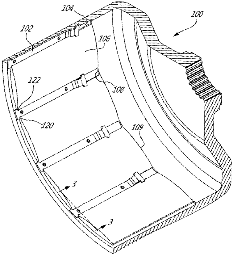
[0060] According to the illustrated embodiment, there is provided a rotor assembly for an external rotor electric machine, the rotor assembly comprising:

[0061] a generally cylindrical rotor body having an interior surface; the generally cylindrical rotor body defining a longitudinal axis of rotation;

[0062] at least two permanent magnets mounted longitudinally to the interior surface of the rotor body, each at least two permanent magnets comprising longitudinally opposed first and second ends and opposed first and second faces a face, the first face configured and sized to contact the interior surface of the rotor body;

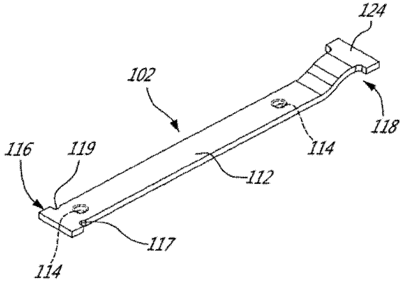
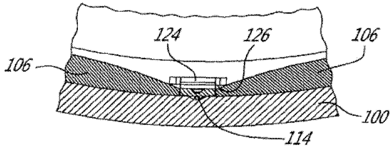
[0063] at least two spacer elements mounted longitudinally to the inner surface of the rotor body and between adjacent permanent magnets via at least one respective weld; the at least two spacer elements are Constructed and sized to resist relative circumferential and radial movement of the permanent magnets relative to the rotor body.

[0064] When th...


PUM


Abstract

The present disclosure is concerned with a permanent magnet rotor for an electric machine provided with an internal stator and a coaxial external rotor. To overcome the drawbacks associated with the use of an adhesive to mount the permanent magnets to the rotor body, permanent magnet retaining elements are mounted to the inner surface of the rotor, between adjacent magnets.

Description

technical field [0001] The present invention relates to permanent magnet electric machines. More specifically, the present invention relates to permanent magnet rotor assemblies including magnet retaining elements welded to the rotor. Background technique [0002] Permanent magnet motors are well known in the art. They usually have a stator and a rotor mounted coaxially to the stator for rotation around the stator. [0003] Some permanent magnet motors have an inner stator and an outer rotor, the rotor roughly enclosing the stator. As in the present case, the rotor has a generally cylindrical body and permanent magnets are positioned on the inner surface of the rotor. To properly mount the permanent magnets to the interior surface of the barrel rotor body, adhesives are conventionally used to prevent relative movement of adjacent permanent magnets. [0004] The use of adhesives between the permanent magnets and the cylindrical rotor body has a number of drawbacks. First...

Claims


Application Information

Patent Timeline
Patent Type & Authority Applications(China)
IPC IPC(8): H02K1/27H02K1/28
CPCH02K1/2786H02K1/2791
Inventor E.拉图利普M.胡勒G.伯苏克S.比格拉斯B.卡朋特D.拉夫拉美J.朗德尔S.弗莱明G.马丁S.罗蒂尔G.加格农S.杜博伊斯
Owner TM4 INC
Why Eureka
Try Eureka