
Horizontal dehydrator

A dehydrator, horizontal technology, applied in the centrifuge and other directions, can solve the problems of screen hole blockage, poor dehydration performance, space blockage, etc., and achieve the effect of preventing screen hole blockage

Active Publication Date: 2013-08-07
JIANGSU FANGSHENG MACHINERY
View PDF6 Cites 0 Cited by
  • Summary
  • Abstract
  • Description
  • Claims
  • Application Information

AI Technical Summary

Problems solved by technology

The outside of the rotor of the centrifugal dehydrator currently used is covered with a sieve cylinder to remove water, and some of these fine debris fall through the sieve holes of the sieve cylinder and fall between the shell of the dehydrator and the sieve cylinder for a long time. It is easy to block the original space, and some even block the sieve holes. At this time, the centrifugal dehydrator will not run smoothly, and the dehydration performance will become worse and worse. Every once in a while, it is necessary to open the dehydrator to clean these small debris, greatly reducing work efficiency

Method used


Image

  • Horizontal dehydrator
  • Horizontal dehydrator

Examples


Embodiment Construction

[0011] The horizontal dehydrator of the present invention will be further described in detail below through specific embodiments.

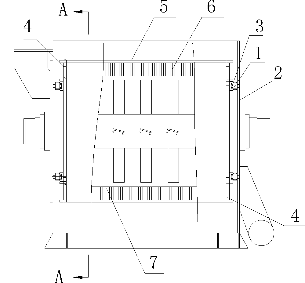
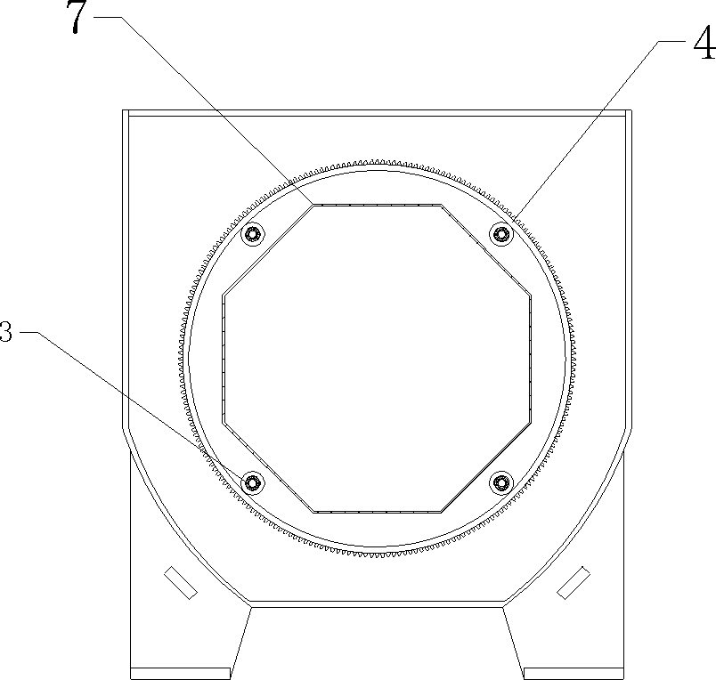
[0012] Such as figure 1 , As shown in 2, the horizontal dehydrator includes a sieve tube 7, in which a rotary centrifugal device is rotatably installed, and both ends of the sieve tube 7 are fixed on the frame by a fixed splint 2. The sieve tube 7 Both ends are sleeved with ring gears 4, and at least two support columns 1 for supporting the ring gear 4 are fixed on each fixing splint 2. In this embodiment, there are 4 support columns. The column 1 is located between the screen cylinder 7 and the gear ring 4. The support column 1 is sleeved with a support bearing 3 on its outer periphery. The support bearing 3 supports the inner wall of the gear ring 4. At least one is installed between the two gear rings 4 The cleaning rod 5 is equipped with a cleaning brush 6 for cleaning the outer peripheral wall of the screen cylinder 7 and the gear ring 4 is driv...


PUM


Abstract

The invention discloses a horizontal dehydrator, which comprises a screen drum. Both ends of the screen drum are fixed onto a frame through fixing clamp plates and sleeved with gear rings, at least two support columns for supporting the gear rings are fixed onto each fixing clamp plate and are positioned between the screen drum and the corresponding gear ring, a support bearing is sleeved on the periphery of each support column and used for supporting the inner wall of each gear ring, at least one cleaning rod is installed between the two gear rings, a cleaning brush for cleaning the peripheral wall of the screen drum is installed on each cleaning rod, and the gear rings are driven by a power device. The horizontal dehydrator can be used for automatically cleaning sieve pores, avoiding blockage of the sieve pores and effectively improving dehydrating efficiency.

Description

Technical field [0001] The invention relates to a dehydrator, in particular to a horizontal dehydrator. Background technique [0002] In the recycling process of waste film and woven bags, there will always be some small scraps. These scraps will all enter the process of drying and dewatering after the process of crushing and cleaning. The rotor of the centrifugal dehydrator currently in use is covered with a sieve tube to remove water, and some of these small scraps pass through the sieve holes of the sieve tube and fall between the shell and the sieve tube of the dehydrator for a long time. It is easy to block the original space, and some even block the sieve holes. At this time, the centrifugal dehydrator will not run smoothly, and the dehydration performance will become worse and worse. You need to open the dehydrator every once in a while to clean these tiny Crushed materials greatly reduce work efficiency. Summary of the invention [0003] The technical problem to be solve...

Claims


Application Information

Patent Timeline
Patent Type & Authority Patents(China)
IPC IPC(8): B04B15/06
Inventor 朱建卫
Owner JIANGSU FANGSHENG MACHINERY
Learn More