Self-locking hydraulic sliding platform

A hydraulic sliding table, self-locking technology, applied in the direction of large fixed members, metal processing machinery parts, metal processing equipment, etc., can solve the problems of affecting the quality of processed workpieces, increasing equipment investment costs, affecting processing efficiency, etc., to achieve simple structure , Good locking effect, and the effect of improving the precision of the workpiece

Active Publication Date: 2015-04-01
JIANGSU ZUZEM VALVES
View PDF5 Cites 1 Cited by
  • Summary
  • Abstract
  • Description
  • Claims
  • Application Information

AI Technical Summary

Problems solved by technology

At this time, only the axial direction (longitudinal direction) of the oil cylinder is used to complete the positioning and tightening, while in the vertical direction perpendicular to the axis of the oil cylinder, due to a certain gap between the sliding worktable and the guide rail working surface of the guide rail body, the locking is not done, and the cutting head is working. Drive the worktable of the hydraulic slide table to vibrate up and down, thus affecting the quality of the processed workpiece
The previous solution was to add another set of hydraulic or mechanical devices to lock the vertical surface, but this not only affects the processing efficiency, but also increases the equipment investment cost

Method used


Image

  • Self-locking hydraulic sliding platform
  • Self-locking hydraulic sliding platform
  • Self-locking hydraulic sliding platform

Examples


Embodiment Construction

[0014] The working principle of this technology will be further described below with the accompanying drawings.

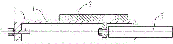
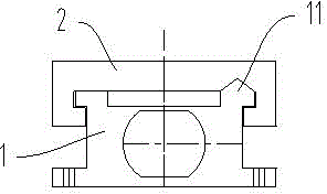
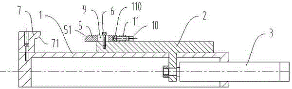
[0015] see Figure 3-5 The self-locking hydraulic slide table shown includes a guide rail body 1, a sliding table 2 sliding along a vertical inverted V-shaped guide rail 11 on the guide rail body, and an oil cylinder 3 for driving the sliding table to move. Adjustment plate 5 is arranged on sliding workbench, and fixed plate 7 is arranged on guide rail body, and two faces of fixed plate and adjustment plate opposite are two matching inclined planes that form 45° with the axis of oil cylinder. When the oil cylinder drives the sliding table to move, the two slopes 71 on the fixed plate 7 contact the slopes 51 on the adjustment plate, and the slopes of the fixed plate generate a downward force on the adjustment plate.

[0016] The adjusting plate is arranged on the sliding workbench by the following structure: the adjusting plate 5 is provided with a slotted hole 9 p...


PUM


Abstract

The invention provides a self-locking hydraulic sliding platform capable of precisely positioning lengthways as well as precisely positioning in a vertical direction. The self-locking hydraulic sliding platform is simply improved based on prior hydraulic sliding platforms, and performs reliable positioning to obviously improve the quality of processed tools. The self-locking hydraulic sliding platform comprises a slideway body, a sliding operating platform in longitudinal sliding movement along the slideway body, and an oil cylinder for driving the sliding operating platform to move, wherein an adjusting plate is arranged on the sliding operating platform; a fixing plate is arranged on the slideway body; two faces of the fixing plate opposite to the adjusting plate are two matching inclined faces; when the sliding operating platform is driven to move by the oil cylinder, the fixing plate is in contact with two inclined faces on the adjusting plate, and a downward acting force is applied to the adjusting plate through the inclined faces of the fixing plate.

Description

technical field [0001] The technology belongs to the field of metal cutting combined machine tools and relates to a self-locking hydraulic slide table. Background technique [0002] The main function of the hydraulic slide table is to cooperate with other functional components in the cutting combination machine tool, such as boring head, milling head, etc. to complete the cutting process of metal products. In the process of processing, it is often necessary for the hydraulic slide table to stop precisely at a certain position. The existing hydraulic slide table comprises a guide rail body 1, a sliding table 2 that slides longitudinally along the guide rail body, and an oil cylinder 3 that drives the sliding table to move (see figure 1 ), the sliding table 2 is slidably arranged on the inverted V-shaped guide rail 11 extending longitudinally along the guide rail body, and the guide rail body 1 is provided with a screw rod 4 that can adjust the axial position. For a long tim...

Claims


Application Information

Patent Timeline
Patent Type & Authority Patents(China)
IPC IPC(8): B23Q1/28
Inventor 夏同华汤伟沈伟许建东肖朋魏顶龙
Owner JIANGSU ZUZEM VALVES
Why Eureka
Try Eureka