
Profiled groove end surface non-contact mechanical seal with backflow function

A mechanical seal, non-contact technology, applied in the direction of engine seals, mechanical equipment, engine components, etc., can solve the problems of high difficulty in implementation, inconspicuous lubricating effect and return effect, and high cost of pumping return type tank technology, to achieve Uniform pressure distribution, improve the carrying capacity of the fluid film, and improve the effect of the pumping effect

Active Publication Date: 2015-04-22
ZHEJIANG UNIV OF TECH
View PDF10 Cites 0 Cited by
  • Summary
  • Abstract
  • Description
  • Claims
  • Application Information

AI Technical Summary

Problems solved by technology

[0004] In order to solve the problems of high cost, high difficulty in implementation, and inconspicuous lubricating and return effects in the existing end face sealing structure, the present invention provides a method that can give full play to the comprehensive effect of the hydrodynamic pressure groove and improve the end face. Non-contact mechanical seal with groove end face and backflow function for lubricating cooling effect and reducing leakage

Method used


Image

  • Profiled groove end surface non-contact mechanical seal with backflow function
  • Profiled groove end surface non-contact mechanical seal with backflow function
  • Profiled groove end surface non-contact mechanical seal with backflow function

Examples


Embodiment Construction

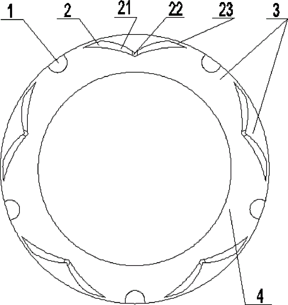
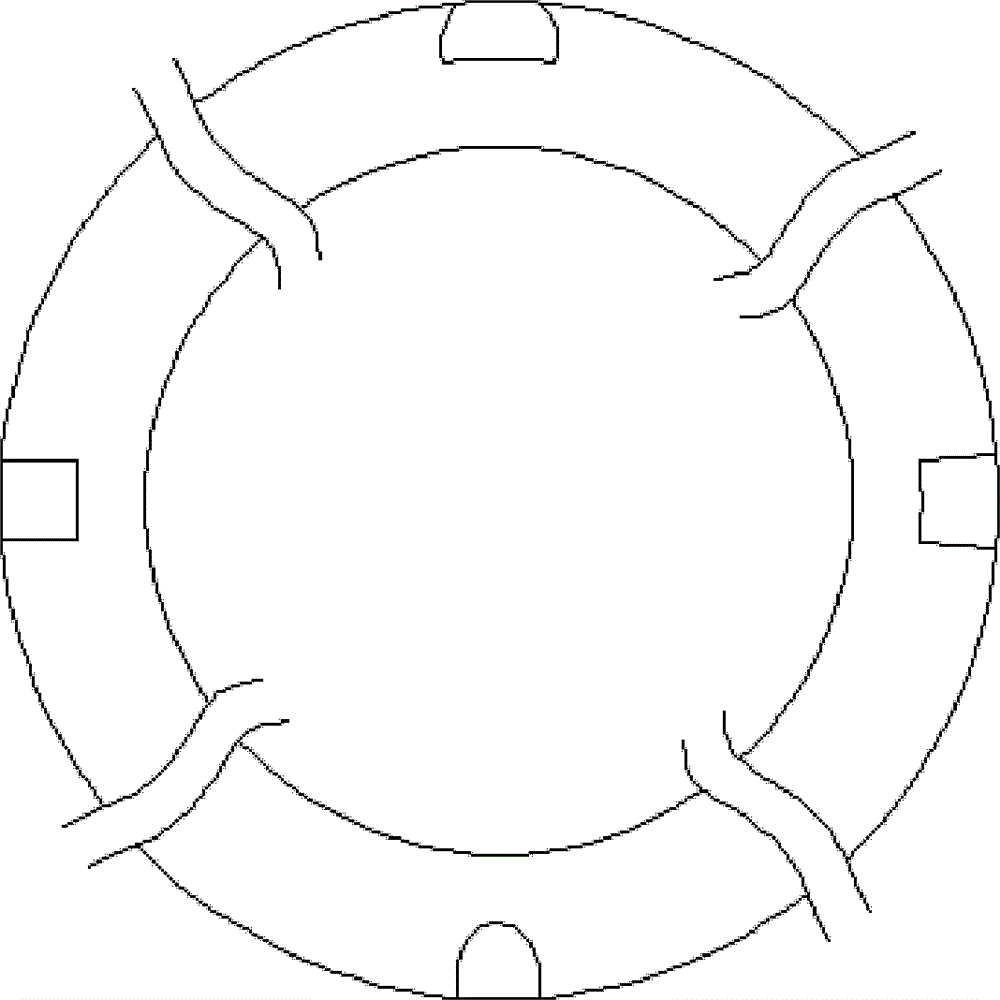
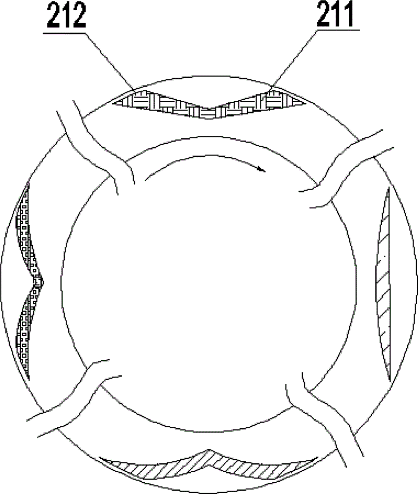
[0028] refer to Figure 1-3 , a grooved end face non-contact mechanical seal with backflow function, including a moving ring and a static ring of the mechanical seal, one side of the end faces of the moving ring and the static ring is the high pressure side, that is, the upstream, the moving ring and the static ring The other side of the end face of the ring is the low-pressure side, that is, the downstream side. A smooth and flat annular sealing dam 4 is provided downstream of the end face, and multiple sets of fluid-type grooves are provided on at least one sealing end face of the moving ring or static ring. The fluid-type grooves are periodically arranged along the circumferential direction of the end surface, and the feature is that: the fluid-type grooves are composed of a drainage groove 1 and a pumping return groove 2, and the average groove depth of the drainage groove 1 is greater than that of the pumping The average groove depth of the reflux groove; the drainage gro...


PUM


Abstract

The invention discloses a profiled groove end surface non-contact mechanical seal with a backflow function. The profiled groove end surface non-contact mechanical seal comprises a mechanical seal moving ring and a mechanical seal static ring, wherein one side of the end surface of each of the moving ring and the static ring is a high-pressure side, i.e. an upstream; the other side of the end surface of each of the moving ring and the static ring is a low-pressure side, i.e. downstream; the downstream of the end surface is provided with an annular sealing dam of a smooth plane; and at least one sealing end surface in the moving ring and the static ring is provided with a plurality of groups of fluid profiled grooves. The profiled groove end surface non-contact mechanical seal with a backflow function is characterized in that the fluid profiled groove is formed by compounding the drainage groove and a pumping reflux groove, wherein the average groove depth of the drainage groove is more than the average groove depth of the pumping reflux groove; the drainage groove is arranged on the upstream of the end surface and is communicated with sealing medium; the pumping reflux groove is the profiled groove with the appearance structure characteristic of a flying bird wing; the groove depth is in the variation rule that the middle is deep and two sides are shallow; and the tail ends of two sides of the pumping reflux groove has a certain space with the upper stream of the end surface. The profiled groove end surface non-contact mechanical seal has dual actions of upstream pumping and downstream pumping to the sealing medium, the leakage amount is reduced, and the operation reliability of sealing is improved.

Description

technical field [0001] The invention relates to a groove end face non-contact mechanical seal with backflow function, which is suitable for the shaft end seal of various centrifugal pumps, screw pumps and other liquid conveying rotating machines, and is especially suitable for the medium that is easy to vaporize and has poor lubricating performance. The sealing belongs to the technical field of fluid sealing. Background technique [0002] Usually, a non-contact mechanical seal device is composed of system components such as a moving ring, a static ring and transmission components, a thrust assembly, an auxiliary sealing ring, and a sealing auxiliary system. In order to improve the working reliability of general mechanical seals, enhance the lubrication effect of the sealing end face, avoid end face wear, and reduce the friction coefficient, a certain surface texture or groove is often set on the end face of the moving ring or static ring, such as spiral groove, T-shaped gro...

Claims


Application Information

Patent Timeline
Patent Type & Authority Patents(China)
IPC IPC(8): F16J15/34F16J15/40
Inventor 彭旭东孟祥铠钮建良李纪云盛颂恩
Owner ZHEJIANG UNIV OF TECH
Learn More