
Valve device with manual override device

A technology for operating devices and valve devices, applied in valve devices, valve operation/release devices, devices to prevent accidental or unauthorized actions, etc., can solve problems such as loss of additional components, increase in manufacturing costs, etc.

Active Publication Date: 2015-01-07
FESTO AG & CO KG
View PDF8 Cites 0 Cited by
  • Summary
  • Abstract
  • Description
  • Claims
  • Application Information

AI Technical Summary

Problems solved by technology

However, this leads to the fact that the valve device has to be equipped with several elements, which can optionally be mounted on the valve unit
Associated with this are increased production costs and the risk that additional components that are not needed temporarily will be lost

Method used


Image

  • Valve device with manual override device
  • Valve device with manual override device
  • Valve device with manual override device

Examples


Embodiment Construction

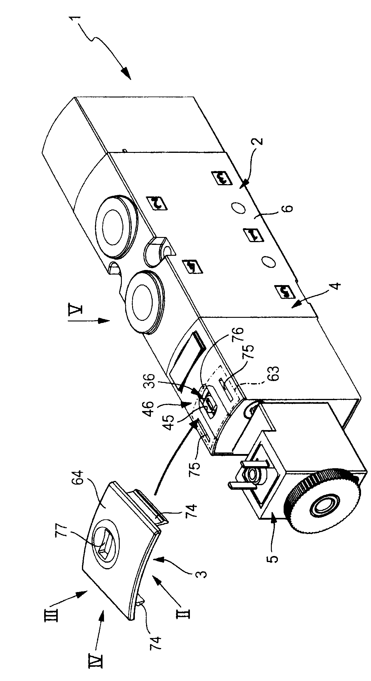
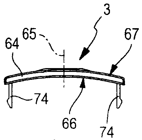
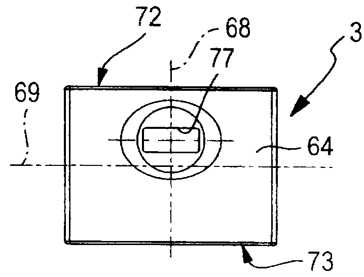
[0043] The figure shows a valve device, designated overall with the reference number 1 , which is assembled from a valve unit 2 and a cover element 3 . exist Figures 2 to 4 , the cover element 3 is also shown again each from a different viewing angle.

[0044] The valve unit 2 is of an electrically actuatable design and is designed in particular as an electrofluidic pilot-controlled multi-way valve. In particular, it is composed of a main valve 4 , which can be actuated by fluid forces, and at least one electrically actuatable pilot valve 5 , which is combined with the main valve 4 as a component.

[0045] The valve unit 2 has a valve housing 6 which is usually constructed in multiple parts, wherein it can be provided in particular that the main valve 4 and the pilot control valve 5 have separate housing parts which are in particular detachably joined together.

[0046] The main valve 4 contains at least one main valve element 7 which is arranged switchably between differen...


PUM


Abstract

#CMT# # / CMT# The valve device (1) has an actuating plunger movably arranged in a valve housing (6). An actuating end section of the plunger is accessible outside the housing. A cover element (3) shields the end section while enabling button actuation against access provided for rotary actuation when the cover element is fixed at the housing in a partial release position. The cover element shields the end section against both the button actuation and the rotary actuation when the cover element is fixed at the housing in a locking position. #CMT#USE : # / CMT# Valve device. #CMT#ADVANTAGE : # / CMT# The cover element shields the actuating end section against both the button actuation and the rotary actuation when the cover element is fixed at the valve housing in the locking position, thus completely preventing actuation of a manual override device in a simple and cost-effective manner during requirement. #CMT#DESCRIPTION OF DRAWINGS : # / CMT# The drawing shows an exploded perspective view of a valve device. 1 : Valve device 2 : Electrically actuatable valve unit 3 : Cover element 4 : Main valve 6 : Valve housing.

Description

technical field [0001] The invention relates to a valve device with an electrically actuatable valve unit having a valve housing, the valve unit being equipped for manual actuation with a hand-assisted actuation device, which is movably arranged on the valve housing An actuating lever in which has an actuating end section accessible from outside the valve housing and which, on the one hand, in the context of push-button actuation, can be moved between an unactuated home position and an actuated working position by pressing the actuating end section On the other hand, in the area of ​​rotary actuation, the rotary actuation end section is releasably locked in the working position with a cover element which can be positioned in a number of different positions relative to the valve housing in order to influence the accessibility of the actuating end section, wherein one of these positions is a partially open position in which the cover element is fastened on the valve housing in s...

Claims


Application Information

Patent Timeline
Patent Type & Authority Patents(China)
IPC IPC(8): F16K31/05
CPCF16K27/003F16K31/06F16K31/0603F16K35/10F16K31/0634
Inventor T·基弗D·舒伯特
Owner FESTO AG & CO KG
Learn More