Flow equalizer

A flow equalizer and shunt tube technology, applied in the direction of branch pipelines, pipes, pipes/pipe joints/fittings, etc., can solve problems such as uneven fluid flow phases, and achieve the effect of improving measurement accuracy

Inactive Publication Date: 2012-07-18
北京中油联自动化技术开发有限公司
View PDF7 Cites 49 Cited by
  • Summary
  • Abstract
  • Description
  • Claims
  • Application Information

AI Technical Summary

Problems solved by technology

[0005] The purpose of the present invention is to provide a new type

Method used


Image

  • Flow equalizer
  • Flow equalizer
  • Flow equalizer

Examples


Embodiment Construction

[0014] The technical solutions of the present invention will be described in further detail below in conjunction with the accompanying drawings and specific embodiments.

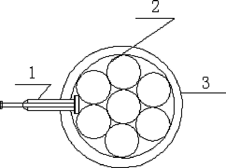
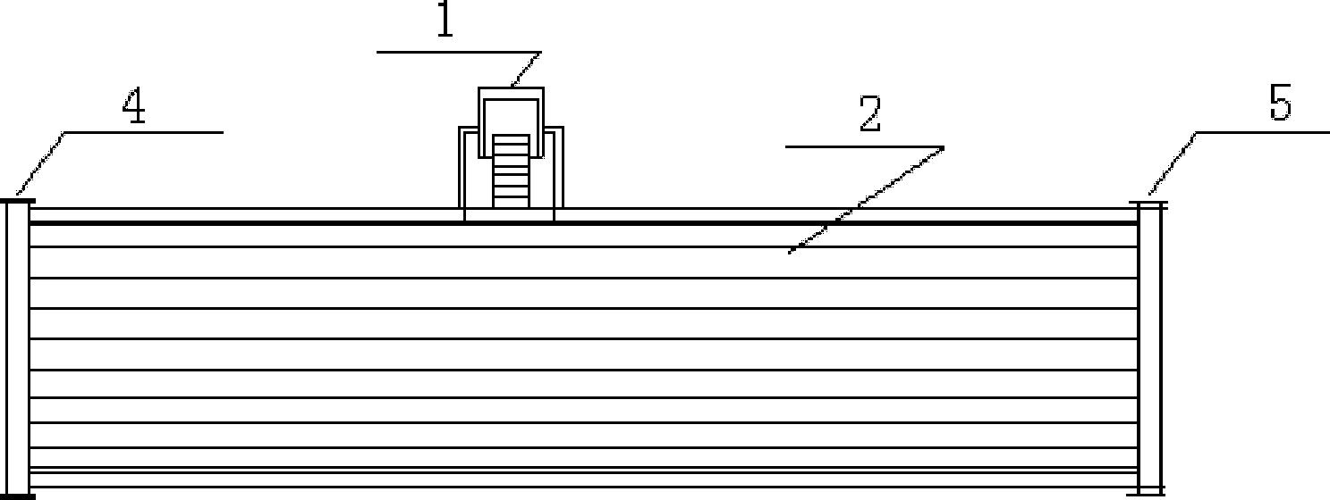
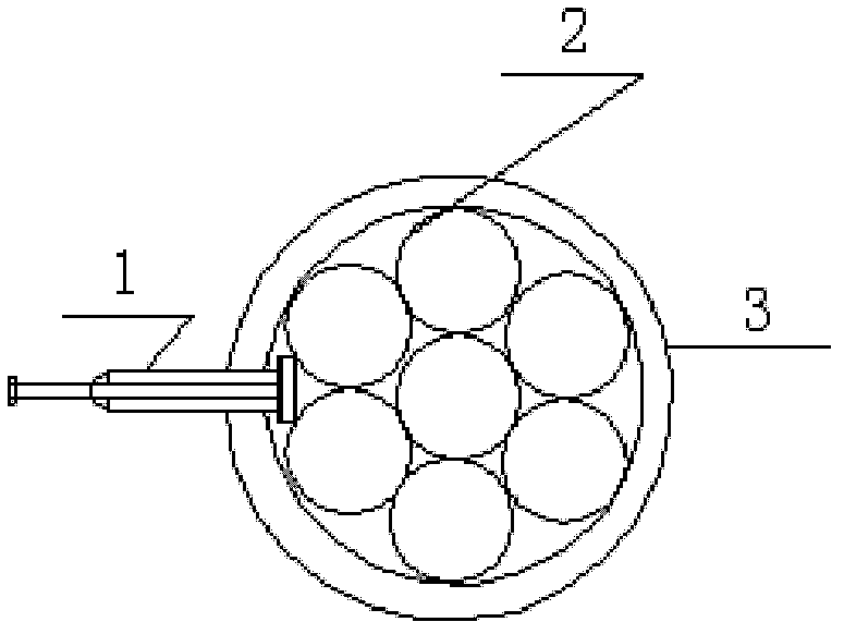
[0015] The structure diagram of a kind of flow equalizer that the present invention proposes, as figure 1 shown. A front sectional view of a current equalizer proposed by the present invention, as figure 2 shown. The flow equalizer includes a shunt pipe 2 and a short flange pipe 3; the shunt pipe 2 is arranged in the short flange pipe 3; an inlet flange 4 is arranged at one end of the short flange pipe 3, and the method The other end of the blue short pipe 3 is provided with an outlet flange 5 . The shunt pipe 2 is fixed in the short flange pipe 3 by a screw holder 1 .

[0016] The flow equalizer is based on fluid characteristics, simulated by fluid simulation software and calculated by calculation software, so as to determine the diameter, quantity and length of the shunt pipe 2 to achieve the purpose ...


PUM


Abstract

The invention provides a flow equalizer, which comprises seven to nineteen distributing pipes (2) and a flange short pipe (3). The distributing pipes (2) are arranged in the flange short pipe (3), an inlet flange (4) is arranged at one end of the flange short pipe (3), and an outlet flange (5) is arranged at the other end of the flange short pipe (3). The distributing pipes (2) are fixed in the flange short pipe (3) through a screw fixator (1). According to the characteristics of fluid, diameter, number and length and the like of the distributing pipes are determined by means of simulation of fluid simulation software and computation of computing software, and accordingly fluid can be stable in flowing states and uniform in distribution by the aid of the distributing pipes. In addition, the flow equalizer is suitable for pump inlets on some process conditions.

Description

technical field [0001] The invention relates to a flow stabilizing device, in particular to a flow equalizer. Background technique [0002] In petroleum, chemical, pharmaceutical, smelting and other industrial factories, there are many requirements for the monitoring of fluid flow, but due to the fluid itself and the fluid pipeline itself, the flow monitoring is not accurate. The traditional solution is to use the flow detection element Straight pipe sections are reserved before and after. This method not only wastes raw materials but also increases a lot of difficulty. [0003] The invention patent number is ZL201120173804.3, and the name of the invention is a steam-water cyclone separator, which includes a separation cylinder, a foam-breaking steel mesh block and a guide flow equalizer; wherein, the foam-breaking steel mesh block is connected to the top of the separation cylinder, and the guide is uniform. The flow device is installed at the bottom of the separation cylin...

Claims


Application Information

Patent Timeline
IPC IPC(8): F16L41/02
Inventor 贺江林
Owner 北京中油联自动化技术开发有限公司
Why Eureka
Try Eureka