Surge protection circuit

A surge protection and circuit technology, applied in emergency protection circuit devices, circuit devices, emergency protection circuit devices for limiting overcurrent/overvoltage, etc., can solve problems such as diode failure, damage, and limitation of electronic device selection. , to reduce the clamping voltage, avoid device damage, and facilitate device selection.

Active Publication Date: 2014-07-30
HUAWEI TECH CO LTD
View PDF9 Cites 0 Cited by
  • Summary
  • Abstract
  • Description
  • Claims
  • Application Information

AI Technical Summary

Problems solved by technology

Therefore, the diode or FET of the shutdown circuit can only be selected with a higher specification. The higher clamping voltage severely limits the selection of electronic devices, and due to the higher clamping voltage, it is easy to cause negative surges when the diode D1 and D2 (or field effect transistors M1 and M2) failure and damage

Method used


Image

  • Surge protection circuit
  • Surge protection circuit
  • Surge protection circuit

Examples


Embodiment Construction

[0018] The following will clearly and completely describe the technical solutions in the embodiments of the present invention with reference to the accompanying drawings in the embodiments of the present invention. Obviously, the described embodiments are only some, not all, embodiments of the present invention. Based on the embodiments of the present invention, all other embodiments obtained by persons of ordinary skill in the art without creative efforts fall within the protection scope of the present invention.

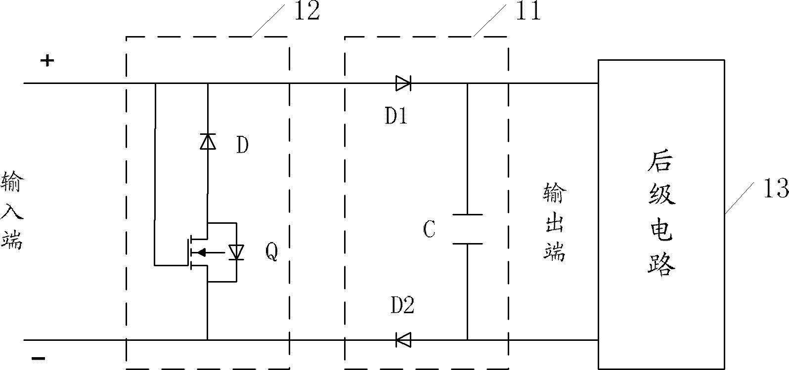
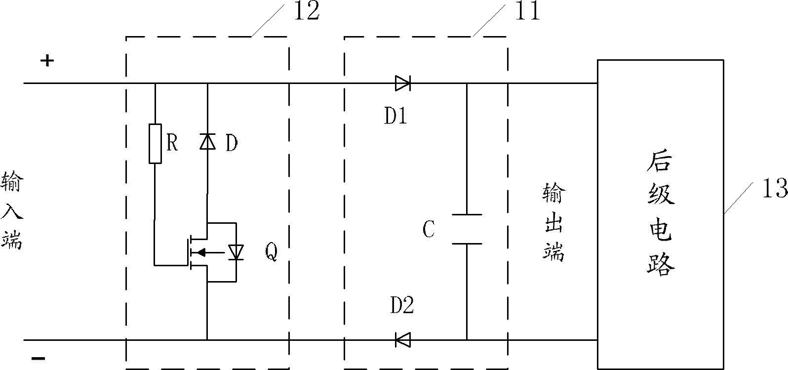
[0019] An embodiment of the present invention provides a surge protection circuit, such as figure 2 As shown, it includes: an input end for providing a DC power supply, an output end for connecting to a subsequent stage circuit 13, a shut-off circuit 11 connected to the output end, and a shut-off circuit connected to the input end and the shut-off circuit Bleeder circuit 12 between.

[0020] Wherein, the discharge circuit 12 includes: a diode D and a field effect...


PUM


Abstract

The invention discloses a surge protection circuit, which relates to the field of power electronics and can reduce the clamping voltage of the negative surge, thereby facilitating device type selection and avoiding device damage caused by the negative surge. The surge protection circuit includes: an input terminal for supplying DC power, an output terminal for connecting to the subsequent stage circuit, and a shutdown circuit connected to the output terminal. The surge protection circuit also includes: an input terminal connected to the The discharge circuit between the circuits; the discharge circuit includes: a diode and a field effect tube; the cathode of the diode is connected to the positive pole of the input terminal, and the anode of the diode is connected to the source of the field effect tube; the gate of the field effect tube is connected to The positive pole of the input terminal, the drain of the field effect transistor are connected to the negative pole of the input terminal, and the direction of the parasitic diode of the field effect transistor is opposite to that of the diode.

Description

technical field [0001] The invention relates to the field of power electronics, in particular to a surge protection circuit. Background technique [0002] At present, in the DC power input or related power systems, in order to prevent negative surges from causing damage to subsequent circuits and equipment, a surge protection circuit is usually installed between the DC input terminal and the subsequent circuits. When there is a surge, the power supply of the subsequent circuit is turned off in time, and the surge current is discharged through the varistor (VR) or transient voltage suppressor (TVS), so as to realize the surge protection of the subsequent circuit. [0003] Specifically, such as figure 1 As shown in (a), the surge protection circuit includes a shutdown circuit and a discharge circuit. The shutdown circuit is specifically as follows: a diode D1 and a diode D2 are respectively arranged at the positive pole and the negative pole of the DC input terminal, wherein...

Claims


Application Information

Patent Timeline
Patent Type & Authority Patents(China)
IPC IPC(8): H02H9/04H02H9/02H02H3/20
CPCH02H9/025H02H11/002H02H9/005H02H1/04H02H9/047H02H9/041
Inventor 彭学文曹文宗
Owner HUAWEI TECH CO LTD
Why Eureka
Try Eureka