Coiling roller for coiling strip steel
A reel and strip steel technology, applied in the field of metallurgy, can solve the problems of strip steel surface quality degradation, strip steel waste, etc., and achieve the effects of improving surface quality, avoiding force mutation areas, and eliminating indentations
- Summary
- Abstract
- Description
- Claims
- Application Information
AI Technical Summary
Problems solved by technology
Method used
Image
Examples
Embodiment 1
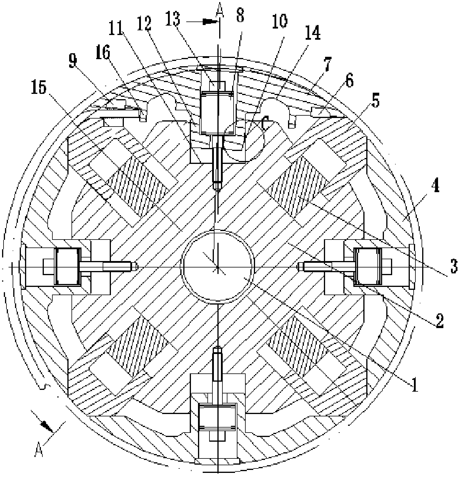
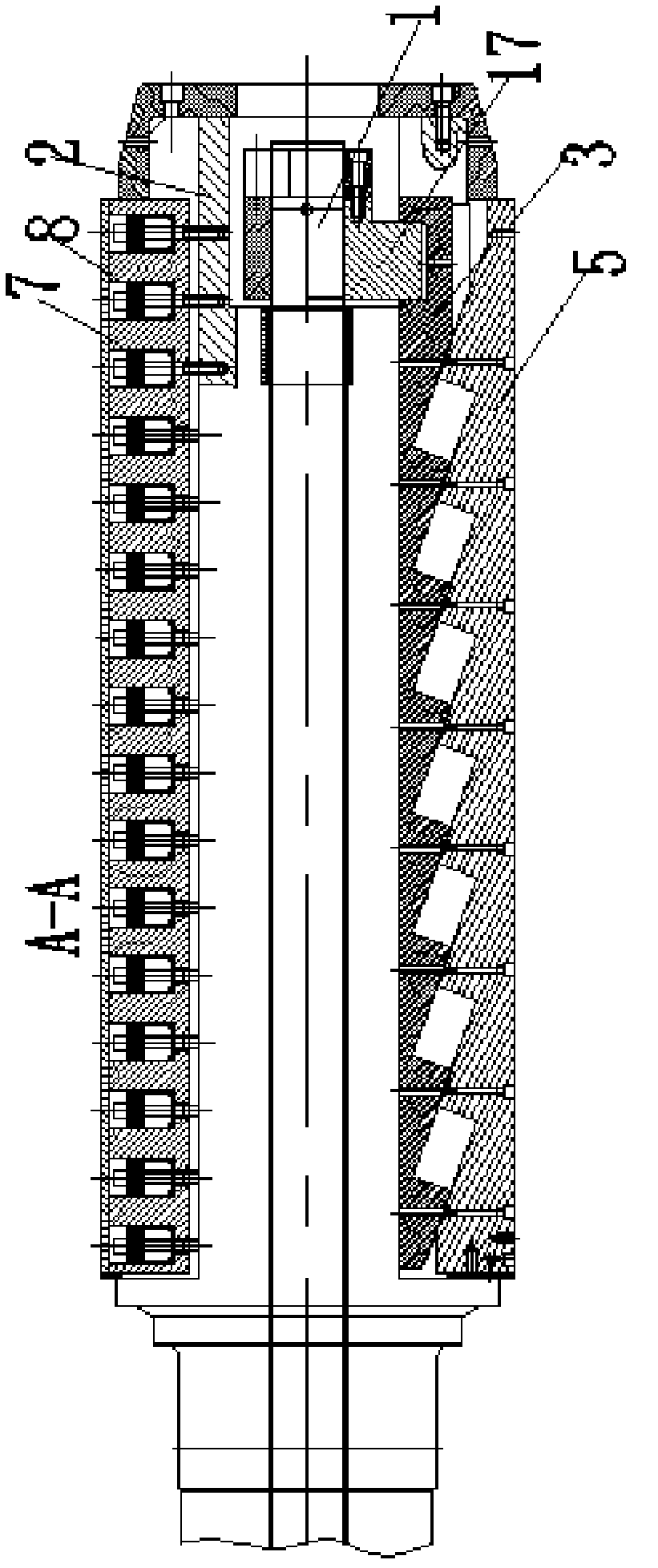
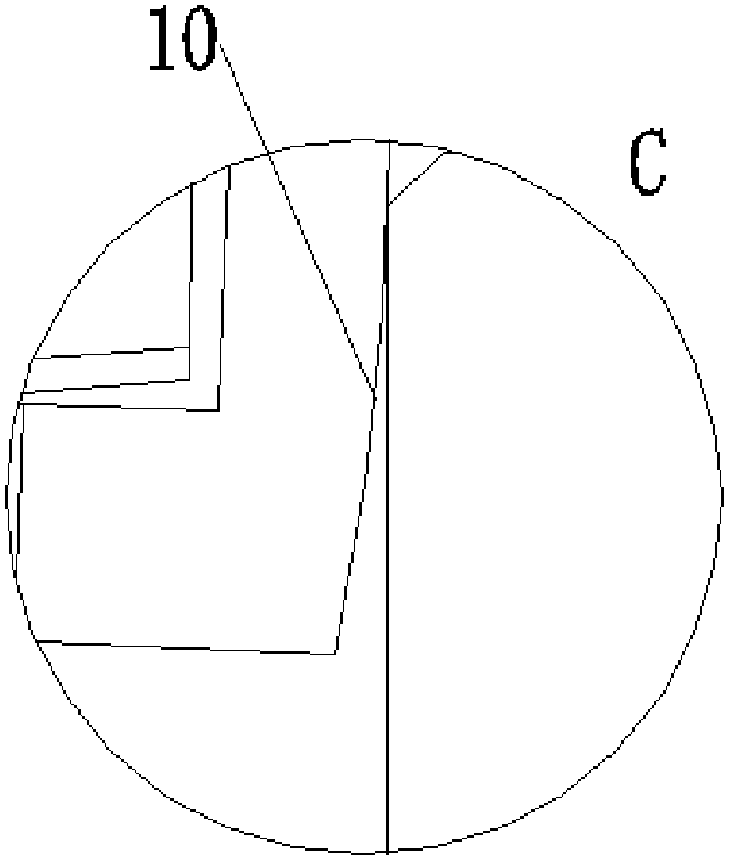
[0020] Refer to attached figure 1 To attach image 3 The shown reel for coiling steel strips includes a pull rod 1, a coiling shaft 2, a closing bar 5 and a fan-shaped plate, and the pull rod 1 is arranged in the through hole at the center of the coiling shaft 2, so that The outer surface of the coiling shaft 2 described above is provided with fan-shaped plates and closing strips 5, the fan-shaped plates include a jaw fan-shaped plate 7 and three common fan-shaped plates 4, the fan-shaped plates are evenly distributed along the circumference of the coiling shaft 2, and the jaws are fan-shaped. The plate 7 can perform circumferential relative rotation and radial expansion and contraction relative to the take-up shaft 2, and the ordinary fan-shaped plate 4 can perform radial expansion and contraction relative to the take-up shaft 2, and is arranged between adjacent fan-shaped plates on the take-up shaft 2 There is a telescopic control assembly that controls the expansion and co...
Embodiment 2
[0022] On the basis of the foregoing scheme, the outer surface of the coiling shaft 2 is provided with a plurality of fan-shaped plate assembly grooves 11, and a guide block 12 corresponding to the fan-shaped plate assembly grooves 11 is provided under the fan-shaped plate. The inside of the guide block 12 is along the A plurality of holes with stepped surfaces are arranged in the axial direction, and bolts 13 and disc springs 8 are arranged in the holes, and the ends of the bolts 13 are connected with the take-up shaft 2 , and guide arc surfaces 10 are arranged on both sides of the guide block 12 .
Embodiment 3
[0024] On the basis of Embodiment 1, further, the telescopic control assembly includes a pull rod 1, an inner wedge 3 and a closing bar 5, grooves are arranged between adjacent fan-shaped plates on the take-up shaft 2, and the inner wedge 3 And the closing strip 5 is arranged in the groove, and a plurality of wedge surfaces are distributed on the outer surface of the inner wedge 3, and the inside of the closing strip 5 is provided with an inclined surface corresponding to the wedge surface, and the inner wedge 3 ends are fixed with nuts. The cross joint 17 at the end of the tie rod 1 is connected. When the pull rod 1 is pulled, the inner wedge 3 can move axially, and then drive the closing bar 5 to move radially, so as to realize the expansion of the fan-shaped plate.
PUM
 Abstract
Description
Claims
Application Information
 - R&D
- Intellectual Property
- Life Sciences
- Materials
- Tech Scout
- Unparalleled Data Quality
- Higher Quality Content
- 60% Fewer Hallucinations
Browse by: Latest US Patents, China's latest patents, Technical Efficacy Thesaurus, Application Domain, Technology Topic, Popular Technical Reports.
© 2025 PatSnap. All rights reserved.Legal|Privacy policy|Modern Slavery Act Transparency Statement|Sitemap|About US| Contact US: help@patsnap.com


