Control system for blow molding air channel

A gas path control and pipeline technology, applied in the field of blow molding gas path control system, can solve the problems of high cost, unstable pre-blowing, large gas pressure fluctuation, etc., and achieve the effect of low cost

Inactive Publication Date: 2012-07-25
JIANGSU NEWAMSTAR PACKAGING MACHINERY
View PDF6 Cites 1 Cited by
  • Summary
  • Abstract
  • Description
  • Claims
  • Application Information

AI Technical Summary

Problems solved by technology

Its disadvantages are: due to the small amount of gas required for pre-blowing, most of the pressurized gas inside the container 4 after molding is discharged, resulting in a large w

Method used


Image

  • Control system for blow molding air channel
  • Control system for blow molding air channel
  • Control system for blow molding air channel

Examples


Embodiment Construction

[0014] A blow molding air path control system of the present invention will be further described in detail through specific embodiments below.

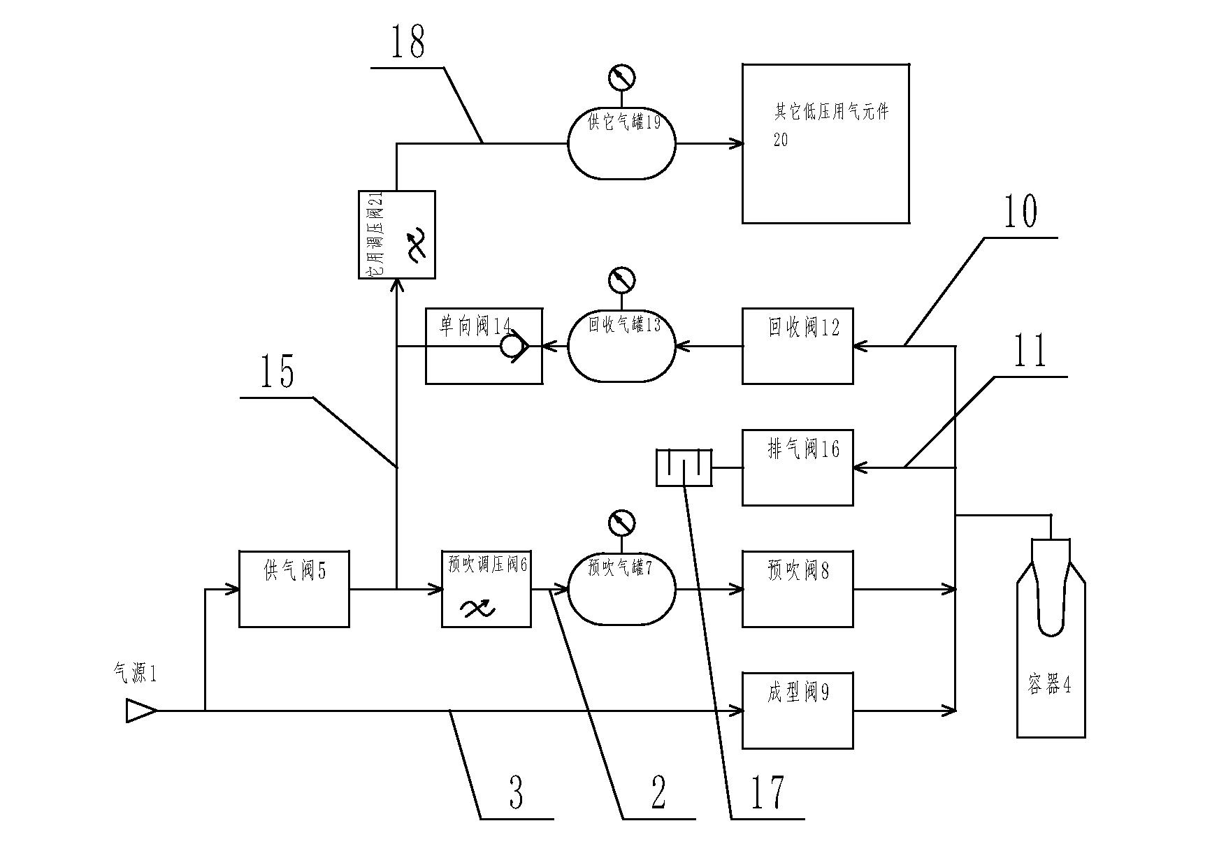
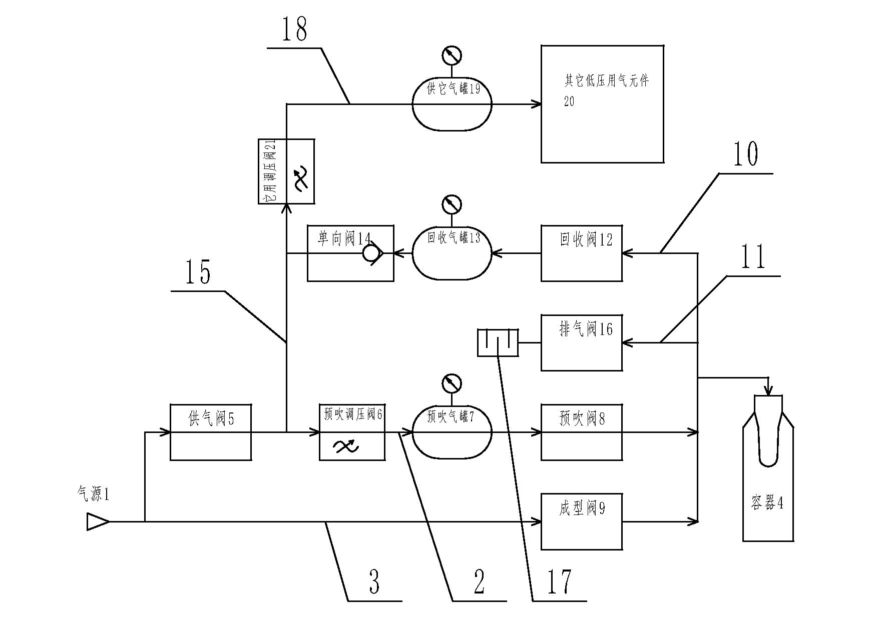
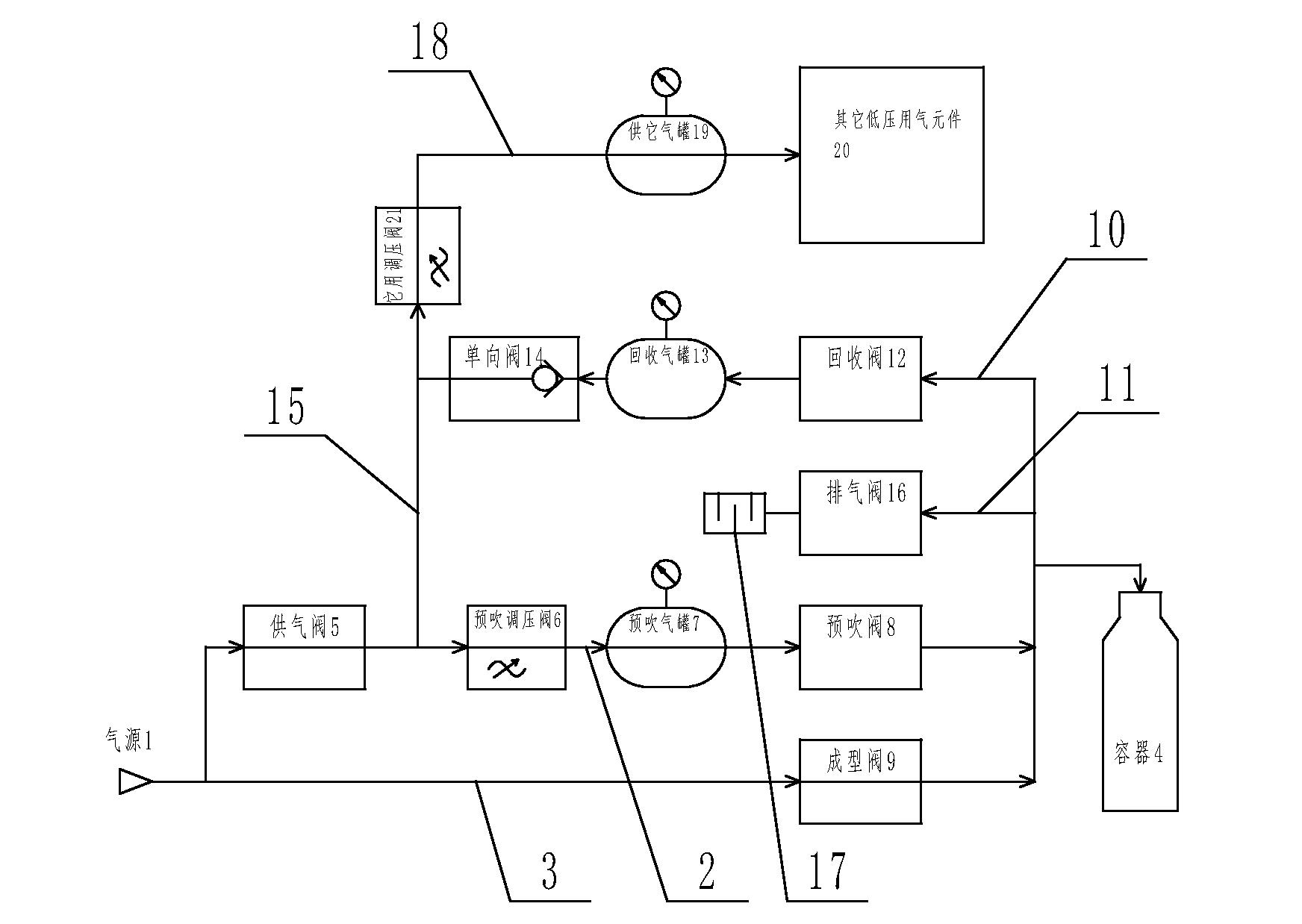
[0015] Such as figure 1 As shown, a blow molding air circuit control system includes a pre-blowing pipeline 2 and a molding pipeline 3 connected to an air source 1 at one end, and the other ends of the pre-blowing pipeline 2 and the molding pipeline 3 are connected to the container to be prepared The 4 phases are connected, and the pre-blowing pipeline 2 is sequentially provided with an air supply valve 5, a pre-blowing pressure regulating valve 6, a pre-blowing gas tank 7 and a pre-blowing valve 8, and a molding valve 9 is set on the molding pipeline 3. In addition, it also includes a recovery pipeline 10 and an exhaust pipeline 11 that one end communicates with the container 4 that needs to be prepared. On the exhaust pipeline 11, an exhaust valve 16 and a muffler 17 are sequentially arranged along the direction of gas flow. The re...


PUM


Abstract

The invention relates to a control system for a blow molding air channel. The control system comprises a pre-blowing pipeline and a forming pipeline, wherein one ends of the pre-blowing pipeline and the forming pipeline are communicated with an air source while the other ends are both communicated with a to-be-prepared container; an air supply valve, a pre-blowing pressure-adjusting valve, a pre-blowing air tank and a pre-blowing valve are arranged on the pre-blowing pipeline in turn; a forming valve is arranged on the forming pipeline; besides, the control system further comprises a recovering pipeline and an exhausting pipeline; one ends of the recovering pipeline and the exhausting pipeline are communicated with the to-be-prepared container; an exhausting valve and a silencer are arranged on the exhausting pipeline in turn; a recovering valve, a recovering air tank and a check valve are arranged on the recovering pipeline in turn; the other end of the recovering pipeline is connected with an air return pipeline and an air supply pipeline; the other end of the air return pipeline is connected with the pre-blowing pipeline, with the joint of the air return pipeline and the pre-blowing pipeline is located between the air supply valve and the pre-blowing valve; an air supply pressure-adjusting valve and an air supply tank are arranged on the air supply pipeline in turn along the air flowing direction; and the other end of the air supply pipeline is connected with the other low-pressure air-consuming component. The control system provided by the invention is suitable for the production of a plastic container.

Description

technical field [0001] The invention relates to a blow molding air circuit control system. Background technique [0002] During the production of plastic containers, two processes of pre-blowing and molding are required, and the pressurized gas in the container must be discharged after molding. Currently used blow molding gas path control system such as Figure 6 As shown, it includes a pre-blowing pipeline 2 and a molding pipeline 3 that are connected to an air source 1 at one end. A gas supply valve 5, a pressure regulating valve 6, an air tank 7 and a pre-blowing valve 8 are arranged in sequence along the direction of the gas flow, and a molding valve 9 is arranged on the molding pipeline 3, and one end is connected with the container 4 to be prepared. recovery pipeline 10 and exhaust pipeline 11, the recovery pipeline 10 is provided with a recovery valve 12, an overflow valve 13 and a first muffler 14 in sequence along the gas discharge direction, between the recovery v...

Claims


Application Information

Patent Timeline
IPC IPC(8): B29C49/78
Inventor 何德平董海龙
Owner JIANGSU NEWAMSTAR PACKAGING MACHINERY
Why Eureka
Try Eureka