Rotary conveyer

A technology of rotary conveying and conveyor belts, which is applied in the direction of conveyors, cleaning devices, conveyor objects, etc., can solve the problems of insufficient conveying power, easy slipping, uneven conveying, etc., achieve stable conveying, stable conveying, and solve the problem of occupying land The effect of the area problem

Inactive Publication Date: 2012-07-25
肇庆市珊瑚食品机械有限公司
View PDF12 Cites 4 Cited by
  • Summary
  • Abstract
  • Description
  • Claims
  • Application Information

AI Technical Summary

Problems solved by technology

In these existing rotary conveyors, the power of the conveyor belt is provided by the active shaft at one end. The disadvantage of this type of conveyor is that the conveyor belt is driven by the friction between the conveyor belt and the shaft, which is easy to appear. Slipping phenomenon, and the problem of insufficient transmission power may occur for long-distance transportation
In addition, the conveyor belt and the bracket are only matched with traditional guide rails, which is also prone to derailment, and the transportation is not stable.

Method used


Image

  • Rotary conveyer
  • Rotary conveyer
  • Rotary conveyer

Examples


Embodiment Construction

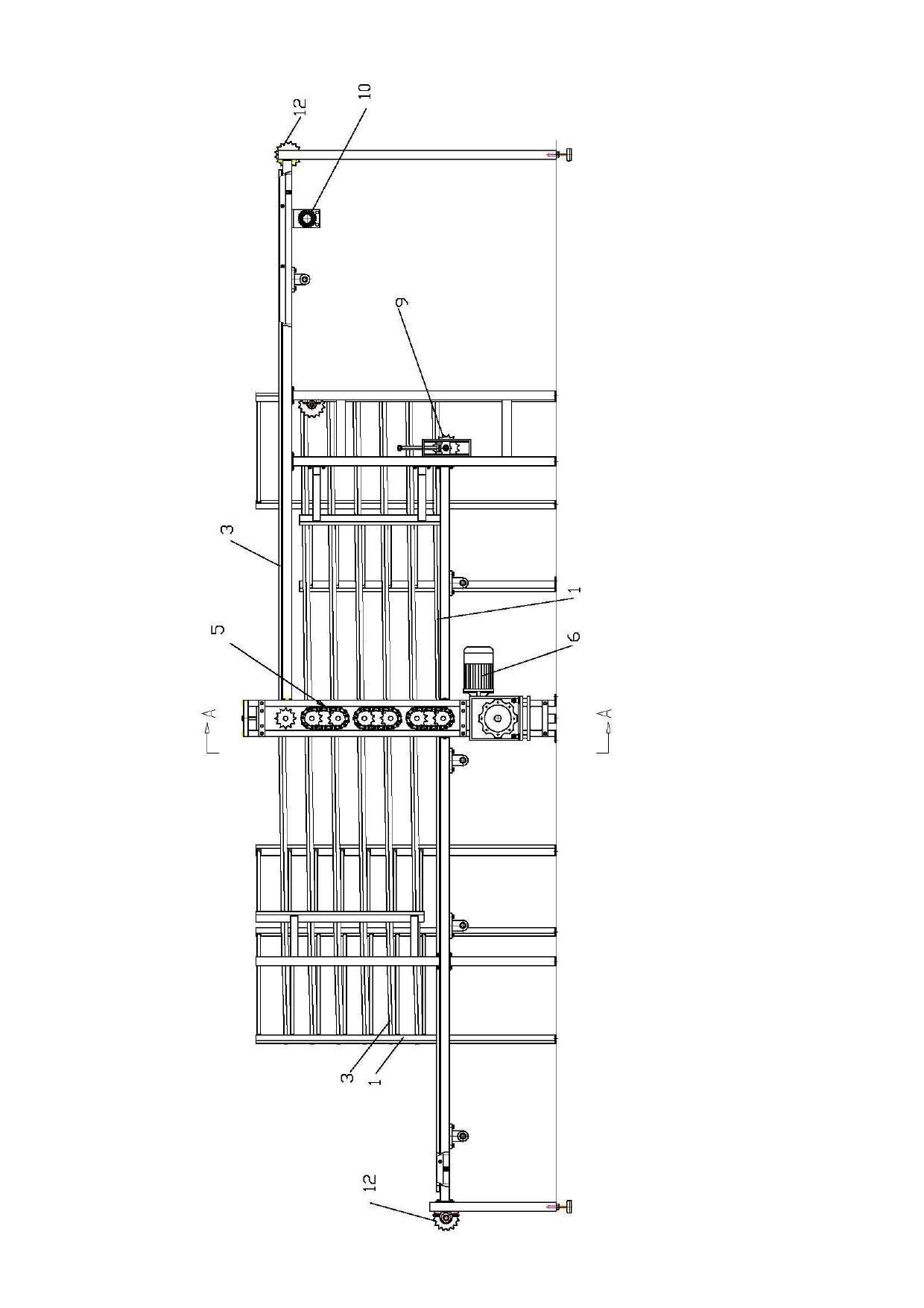
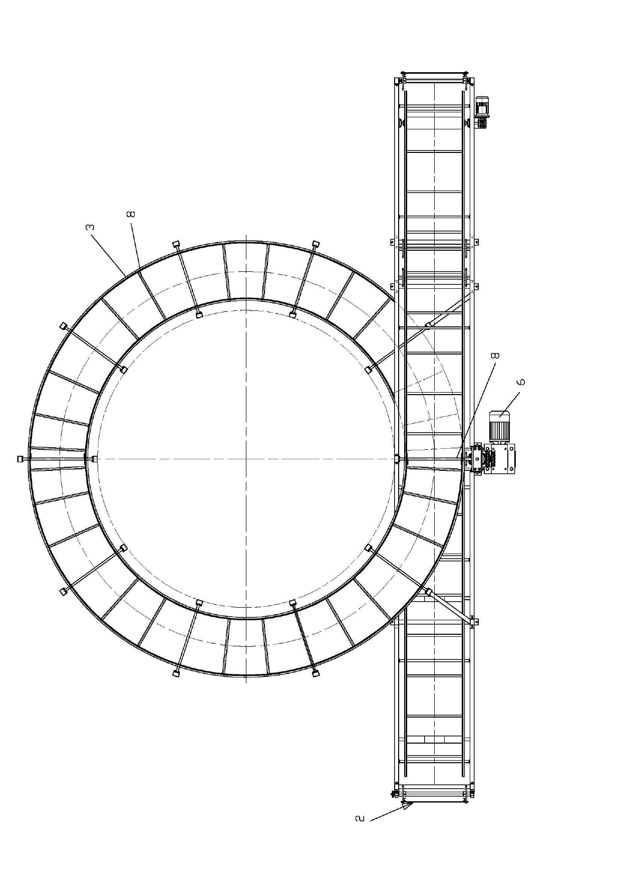
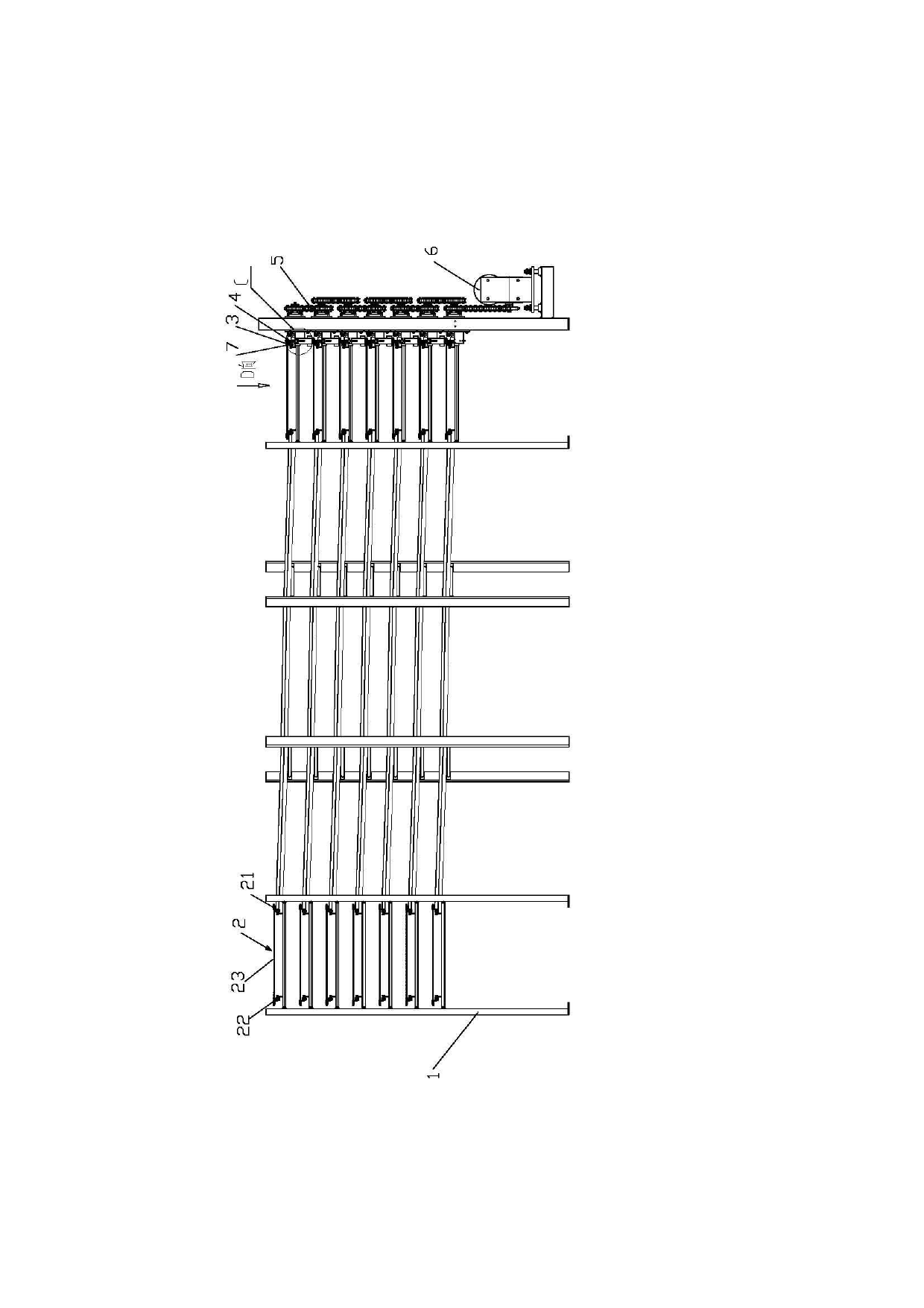
[0020] figure 1 , 2 , 3, 4 and 5, the rotary conveying device of the present invention includes a rotating frame 1 and a conveying mesh belt 2, wherein the conveying mesh belt is fixed inside and outside by inner and outer circulating conveyor belts 21, 22, The mesh belt 23 on the outer circulation conveyor belt 21, 22 is composed of a guide rail 3 on the rotating frame 1, and a mesh belt sprocket 4 matched with the outer circulation conveyor belt 22 is provided on each layer of the rotating frame 1. The belt sprocket 4 is connected to the motor 6 through the transmission mechanism 5; on the conveying mesh belt 2, there is also a limit block 7 that matches the guide rail 3, and the cross-sectional shape of the limit block 7 is an inverted U-shaped structure , The limiting block 7 is in contact with the inner upper surface and the inner surface on the annular guide rail 3, which not only plays a position limiting role, but also makes it slide on the smooth guide rail 3 surface...


PUM


Abstract

The invention discloses a rotary conveyer, which comprises a rotary frame and a conveying mesh belt. The conveying mesh belt comprises an inner circulatory conveying belt, an outer circulatory conveying belt and a mesh belt fixed on the inner and the outer circulator conveying belts. The rotary frame is provided with guides. Mesh belt sprockets matched with the outer circulatory conveying belt are arranged on each layer of the rotary frame and in transmission connection with a motor through a transmission mechanism. Limit blocks matched with guides are further disposed on the conveying mesh belt. The rotary conveyer is small in occupied area and stable in conveying.

Description

technical field [0001] The invention relates to a belt conveying device, in particular to a rotary conveying device. Background technique [0002] At present, in order to extend the conveying path under the condition of reducing the occupied area in order to meet the needs of continuous production, people have set up equipment with various roundabout rotary conveying devices. In these existing rotary conveyors, the power of the conveyor belt is provided by the active shaft at one end. The disadvantage of this type of conveyor is that the conveyor belt is driven by the friction between the conveyor belt and the shaft, which is easy to appear. Slipping phenomenon, and the problem of insufficient transmission power may occur for long-distance transportation. In addition, only traditional guide rails are used to cooperate between the conveyor belt and the bracket, which is also prone to derailment, and the transportation is not stable. Contents of the invention [0003] The ...

Claims


Application Information

Patent Timeline
Patent Type & Authority Applications(China)
IPC IPC(8): B65G15/22B65G21/22B65G21/00B65G45/10B65G23/44B65G23/24B65G23/06
Inventor 冯炳俦
Owner 肇庆市珊瑚食品机械有限公司
Why Eureka
Try Eureka