Spinning machine with compact equipment

A technology of spinning machine and equipment, applied in the field of spinning machine with compact equipment, can solve the problem that the moving cylinder fan cannot be eliminated, and achieve the effect of simplifying improvement and simplifying assembly

Active Publication Date: 2012-07-25
MASCHINENFABRIK RIETER AG
View PDF10 Cites 0 Cited by
  • Summary
  • Abstract
  • Description
  • Claims
  • Application Information

AI Technical Summary

Problems solved by technology

The use of moving cylinder fans guided past the spinning position at regular intervals does not eliminate this problem

Method used


Image

  • Spinning machine with compact equipment
  • Spinning machine with compact equipment
  • Spinning machine with compact equipment

Examples


Embodiment Construction

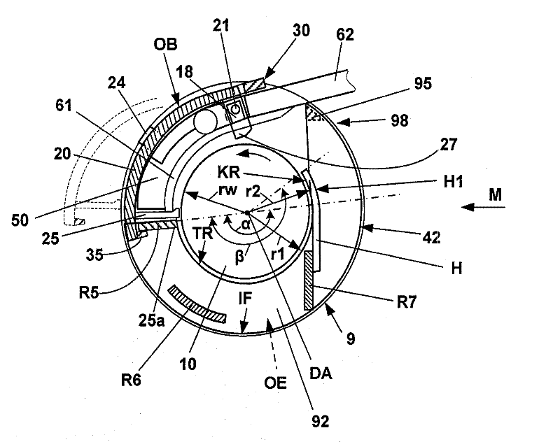
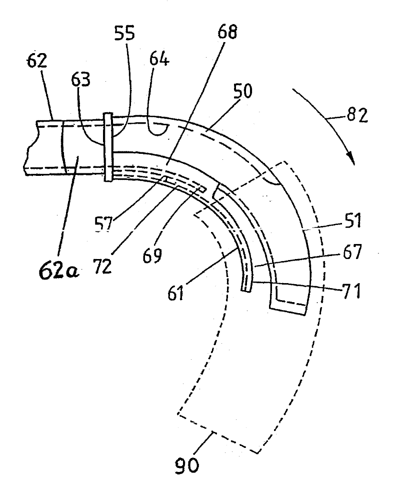
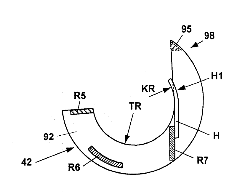
[0029] figure 1 represents a drafting system unit 1 (of a plurality of drafting system devices arranged next to each other) of a not shown spinning machine (for example, a ring spinning machine), wherein in this example the drafting system unit consists of three pairs Rolla poses. These are formed by the incoming roller pair 2,3 followed by the central roller pair 5,6. The preparation yarn F (roving) drawn off from a roving drum not shown is conveyed to the drafting system unit 1 by means of intake rollers 2 , 3 . When compared to the twisting speed of the introduction rollers 2, 3, the twisting speed of the center rollers 5, 6 is slightly increased, so that an untwisting draft of the roving F is produced between this pair of rollers. Small conveyor belts 11 , 12 are in each case guided around central rollers 5 , 6 which are held in position where they are shown around rollers not shown in any detail. After leaving the nip line Z1 between the central rollers 5 , 6 , the unt...


PUM


Abstract

The invention relates to a covering device (42) for suction drums (9), one of compacting devices adjacent drafting units of a spinning machine, wherein the suction drums (9) are disposed coaxially on a longitudinal shaft (10) and on their axially spaced apart, opposite sides annular opening (OE), through each of which a suction source connected to a suction liner (50) projects into the interior of the respective suction drum. To the interior of the suction drums (9) to protect against contamination and uncontrolled air currents, it is proposed that the capping device (42) between the adjacent suction drums (9) is attached and from the opposite which is connected to webs (R1, R2, R3, R4) covering elements (84, 85) exists, each of the adjacent to the respective suction insert remaining annular openings (OE) of the suction drums face (9) and overlapping this at least partially.

Description

technical field [0001] The invention relates to a covering device for a suction cylinder of a compacting device of an adjacent drafting system unit of a spinning machine, wherein said suction cylinder is arranged coaxially on a longitudinal axis and in each case On their axially opposite sides at a distance from each other there is an annular opening through which a suction insert connected in each case to a suction source protrudes into the interior of the suction cylinder. Background technique [0002] Such a device is shown and described, for example, in DE 10 2005 044 967 . In this respect, a removable suction insert with a suction opening is arranged in the adjacent suction cylinder of the double drafting system. A double drafting system consists of two adjacently arranged drafting system units having a common pressure arm carrying a pressure cylinder. The suction opening of the suction insert is placed in connection with the suction channel, the outlet opening of the...

Claims


Application Information

Patent Timeline
Patent Type & Authority Applications(China)
IPC IPC(8): D01H5/72
CPCD01H5/72
Inventor R.迈尔R.纳格利G.施奈德
Owner MASCHINENFABRIK RIETER AG
Why Eureka
Try Eureka