
Hydraulic energy-saving system and hydraulic hoisting device

An energy-saving system and hydraulic energy technology, applied in mechanical equipment, fluid pressure actuating devices, servo motors, etc., can solve problems such as failure to take into account and reduce energy utilization, improve stability, avoid charging shock, and reduce unintended consequences. The effect of stabilizers

Active Publication Date: 2012-07-25
SANY MARINE HEAVY IND +1
View PDF6 Cites 20 Cited by
  • Summary
  • Abstract
  • Description
  • Claims
  • Application Information

AI Technical Summary

Problems solved by technology

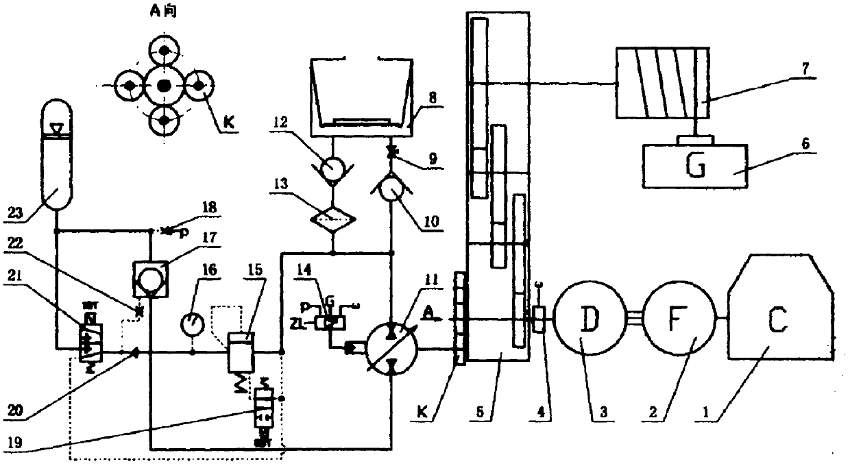
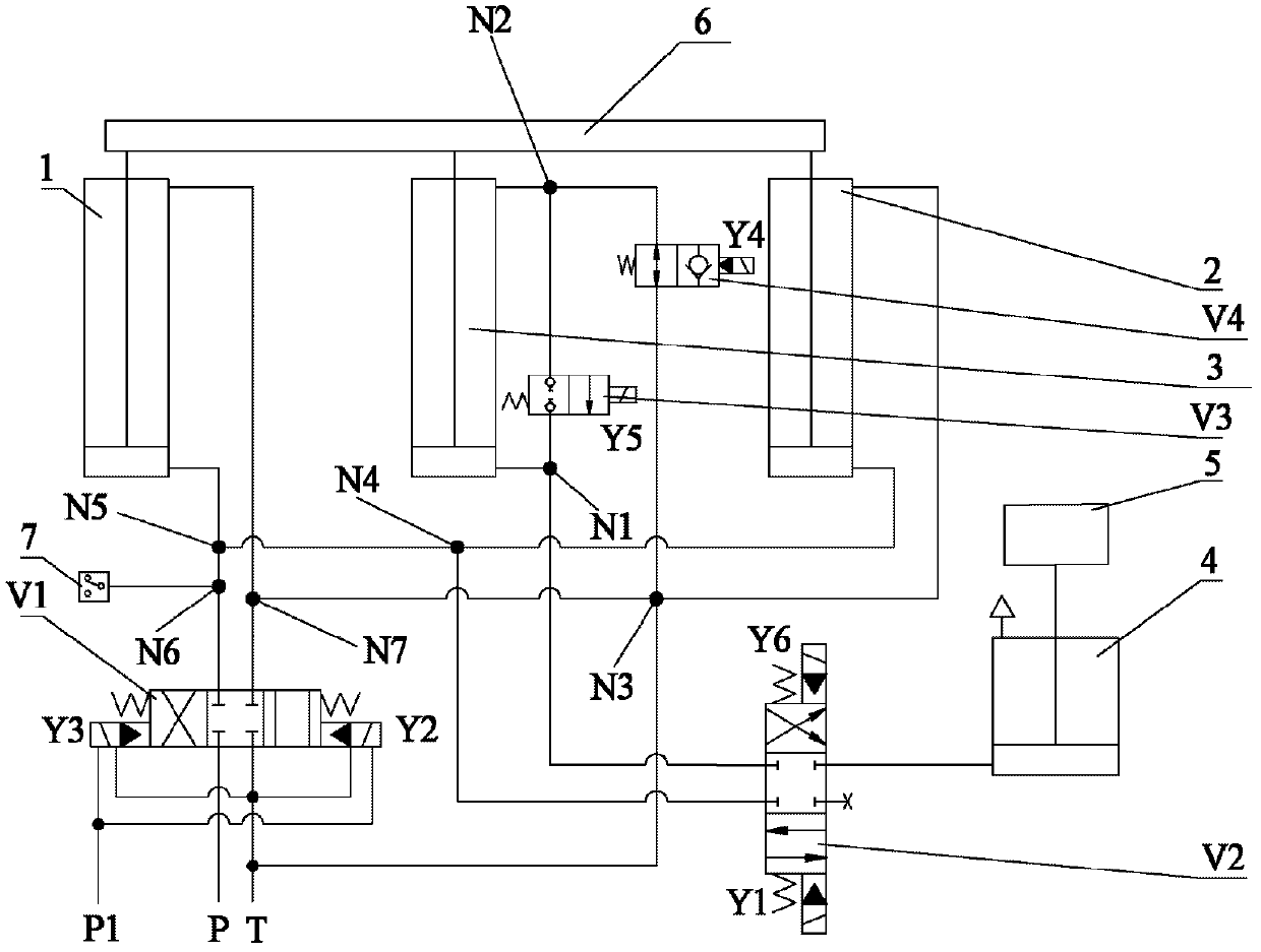
In an energy-saving system using an accumulator, the performance of the accumulator changes with parameters such as pressure and temperature. Therefore, figure 1 and figure 2 The hydraulic energy-saving systems shown have common shortcomings, that is, they do not consider how to store the recovered energy in the accumulator stably and more, so as to minimize the impact on the accumulator caused by changes in parameters such as pressure and temperature. performance, thereby reducing the instability of the energy-saving system; at the same time figure 1 The gear pair energy release transmission mechanism used in the system greatly reduces the energy utilization rate and becomes an urgent technical problem to be solved

Method used


Image

  • Hydraulic energy-saving system and hydraulic hoisting device
  • Hydraulic energy-saving system and hydraulic hoisting device
  • Hydraulic energy-saving system and hydraulic hoisting device

Examples


Embodiment Construction

[0044] In order to understand the above-mentioned purpose, features and advantages of the present invention more clearly, the present invention will be further described in detail below in conjunction with the accompanying drawings and specific embodiments.

[0045] In the following description, many specific details are set forth in order to fully understand the present invention, but the present invention can also be implemented in other ways different from those described here, therefore, the present invention is not limited to the specific embodiments disclosed below limit.

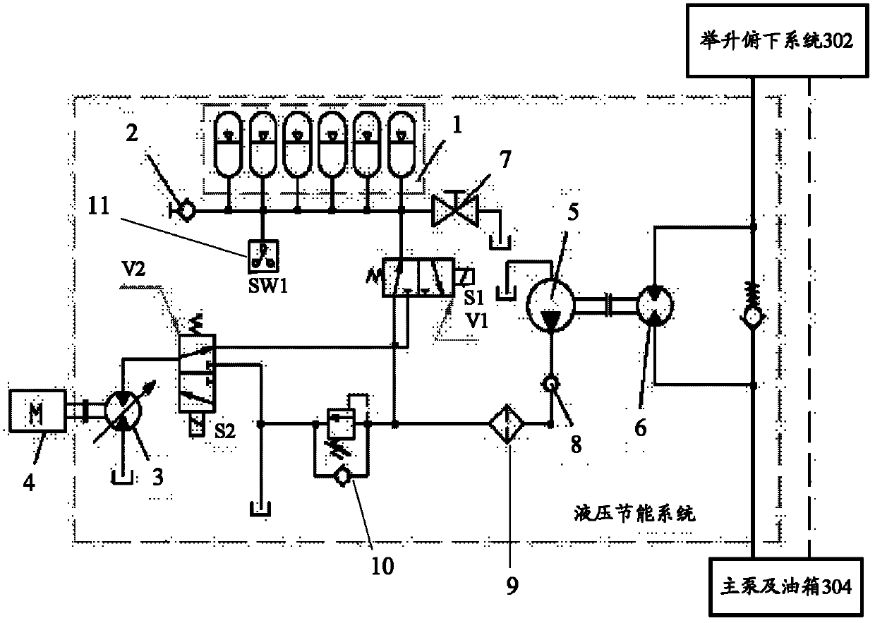
[0046] First please refer to image 3 , according to the hydraulic energy saving system of the embodiment of the present invention, comprising: the first load (such as image 3 lift down system shown in ), a second load (such as image 3 shown in the engine 4), the first hydraulic motor 6, the second hydraulic motor 3, the hydraulic pump 5 and the accumulator, wherein the potential energy generated ...


PUM


Abstract

The invention provides a hydraulic energy-saving system, which comprises a first load, a second load, a first hydraulic motor, a second hydraulic motor, a hydraulic pump and an energy storage device. Potential energy generated during operation of the first load drives the first hydraulic motor which drives the hydraulic pump to rotate, and hydraulic energy generated by the hydraulic pump is stored in the energy storage device or drives the second hydraulic motor to rotate which drives the second load to rotate. According to the technical scheme, pressure energy of a pressure oil source can be recycled stably and maximally. The second hydraulic motor performs torque compensation on the second load so that the pressure energy can be released stably for a long time. The hydraulic energy-saving system is separated from an operation system so that stability of the system is improved, and loss is reduced. The invention further provides a hydraulic hoisting device with the hydraulic energy-saving system.

Description

technical field [0001] The invention relates to the field of engineering machinery, in particular to a hydraulic energy-saving system and hydraulic lifting equipment with the hydraulic energy-saving system. Background technique [0002] The hydraulic system has a wide range of applications in construction machinery, such as using the high-pressure oil of the hydraulic system to drive the lifting and lowering system to lift heavy objects, and for example using the high-pressure oil to drive the brake system for effective braking. [0003] Hydraulic lifting equipment frequently lifts / lowers heavy objects during operation. When lifting, the engine drives actuators, such as hydraulic cylinders. Corresponding potential energy will be generated, and the hydraulic oil will be returned directly to the oil tank, and this part of potential energy will not be recovered, resulting in energy waste. If the potential energy can be collected and the recovered energy can be reused, the ener...

Claims


Application Information

Patent Timeline
IPC IPC(8): F15B9/16
Inventor 彭天乐金晶赵庆辉
Owner SANY MARINE HEAVY IND
Learn More