
Combustor nozzle and method for fabricating the combustor nozzle

A combustion chamber and nozzle technology, applied in combustion methods, combustion chambers, continuous combustion chambers, etc., can solve the problems of high demand for inspection and repair, high production costs, etc.

Active Publication Date: 2012-07-25
GENERAL ELECTRIC TECH GMBH
View PDF7 Cites 3 Cited by
  • Summary
  • Abstract
  • Description
  • Claims
  • Application Information

AI Technical Summary

Problems solved by technology

These joints are relatively expensive to produce and require greater inspection and repair

Method used


Image

  • Combustor nozzle and method for fabricating the combustor nozzle
  • Combustor nozzle and method for fabricating the combustor nozzle
  • Combustor nozzle and method for fabricating the combustor nozzle

Examples


Embodiment Construction

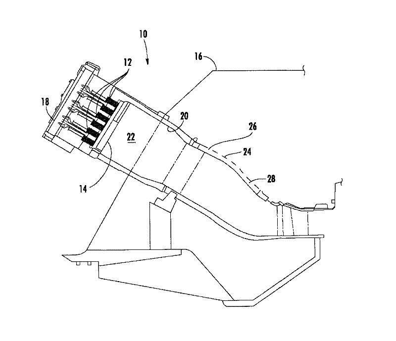
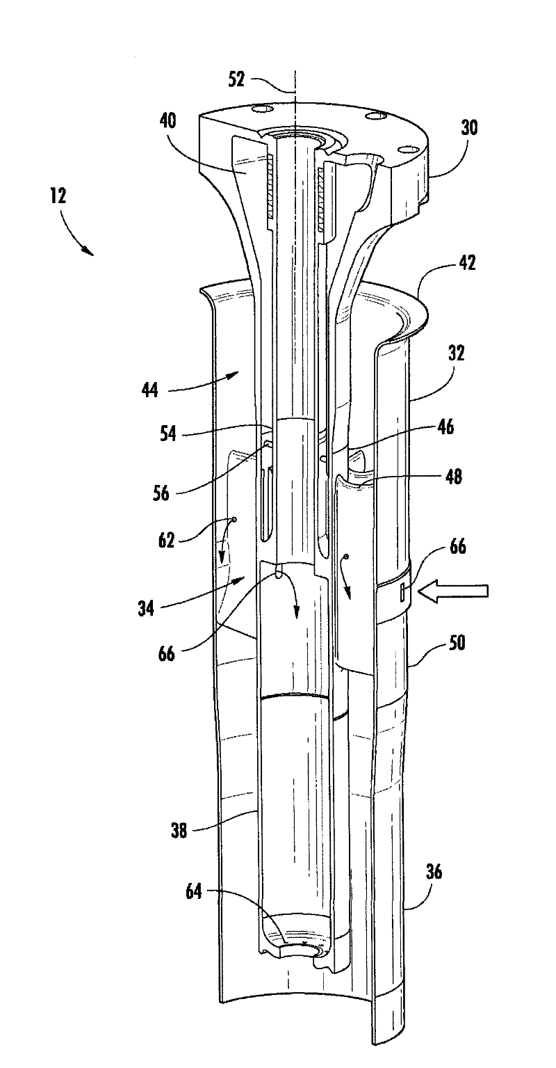
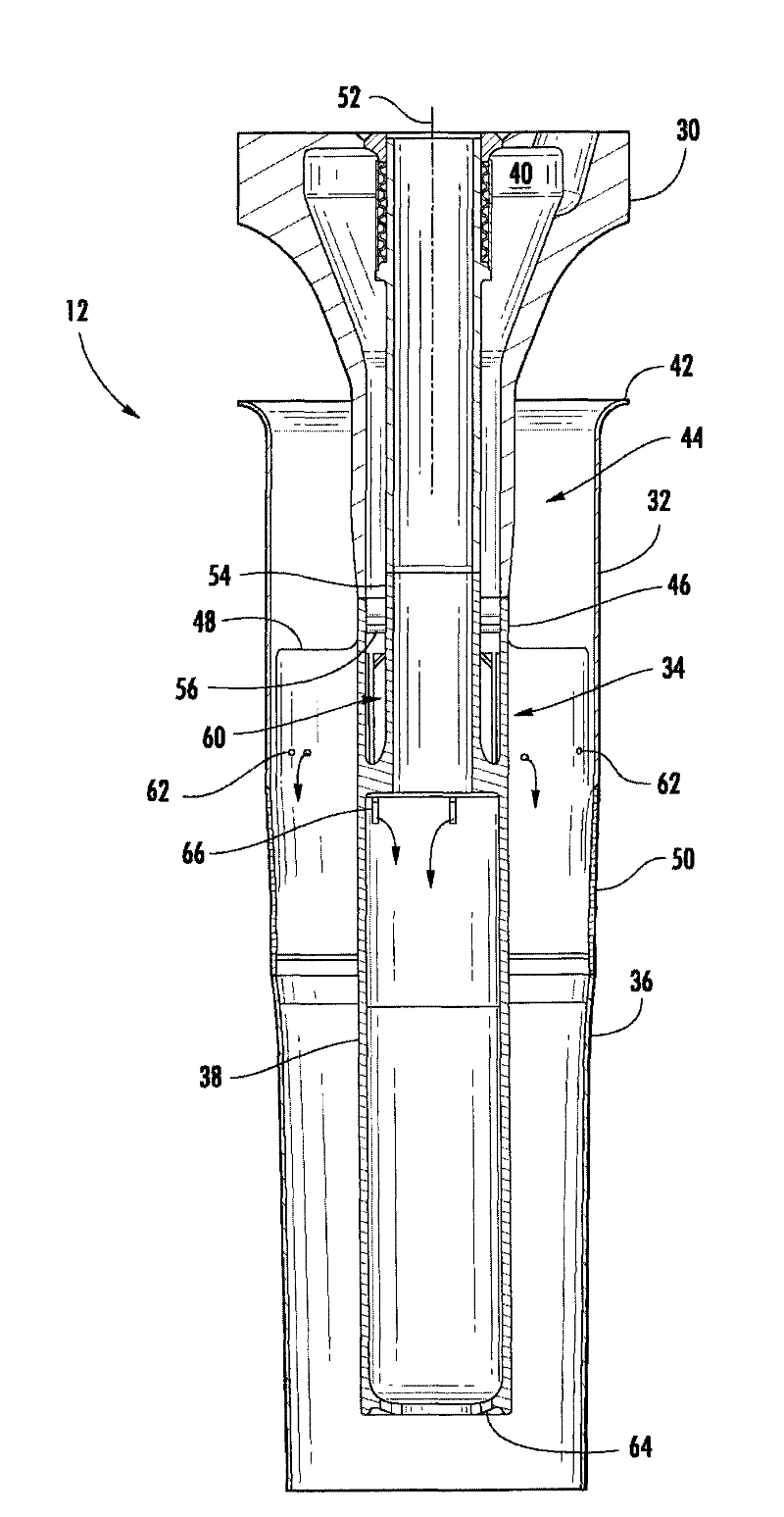
[0023] Embodiments of the invention will now be described in detail with reference to the accompanying drawings, in which one or more examples of the invention are illustrated. Numeral and letter designations are used in the detailed description to refer to component features in the drawings. The same or similar symbols in the drawings and description are used to refer to the same or similar parts of the present invention.

[0024] Each example is provided by way of explanation of the invention, not limitation of the invention. In fact, various modifications and variations can be made in the present invention by those skilled in the art without departing from the scope or spirit of the invention. For example, features described as part of one embodiment can be used on other embodiments to yield a still further embodiment. Accordingly, the present invention should cover all modifications and changes within the scope of the appended claims and their equivalents.

[0025] fig...


PUM


Abstract

A combustor nozzle includes a single-piece swirler. The single-piece swirler includes a center body extending axially along the single-piece swirler, a first fuel passage inside the center body, and a plurality of vanes extending radially from the center body. A method for fabricating a combustor nozzle includes casting a single-piece swirler having a center body and a plurality of vanes extending radially from the center body.

Description

technical field [0001] The present invention generally relates to combustor nozzles and methods of making combustor nozzles. Background technique [0002] Combustion chambers are known in the art for igniting a mixture of fuel and air for generating combustion gases having high temperature and pressure. For example, gas turbine systems, aircraft engines, and many other combustion-based systems include one or more combustors that mix a working fluid, such as air, with fuel and then ignite the mixture, producing high-temperature, high-pressure combustion gases. Each combustor generally includes one or more nozzles for mixing a working fluid and fuel prior to combustion. If the fuel and air are not mixed well prior to combustion, localized hot spots can form in the combustion chamber. Localized hot spots may increase unwanted NOx emissions and also increase the chance of flames within the combustion chamber flashing back into and / or becoming lodged in the nozzle, thereby dama...

Claims


Application Information

Patent Timeline
Patent Type & Authority Applications(China)
IPC IPC(8): F23R3/38
CPCF23R3/286F23R3/14Y02T50/675F23C2900/07001B22D25/00F23D2900/00008F23R2900/00018Y02T50/60
Inventor D·M·贝利W·L·贝尔恩P·B·梅尔顿
Owner GENERAL ELECTRIC TECH GMBH
Features
  • Generate Ideas
  • Intellectual Property
  • Life Sciences
  • Materials
  • Tech Scout
  • Unparalleled Data Quality
  • Higher Quality Content
  • 60% Fewer Hallucinations
Learn More