Guidewire

A wire and coil technology applied to wires. In the field, it can solve the problems of easy plastic deformation and achieve the effect of preventing plastic deformation and good torque force

Inactive Publication Date: 2012-08-01
ASAHI INTECC CO LTD
View PDF1 Cites 4 Cited by
  • Summary
  • Abstract
  • Description
  • Claims
  • Application Information

AI Technical Summary

Problems solved by technology

That is, plastic deformation is likely to occur at a position away from the distal end portion of the guide wire (the front end portion of the mandrel)

Method used


Image

  • Guidewire
  • Guidewire
  • Guidewire

Examples


no. 1 approach

[0050] Hereinafter, a first embodiment which is one embodiment of the lead wire of the present invention will be described with reference to the drawings.

[0051] The lead wire of this embodiment has the same structure as the lead wire of the present invention described above, so the following reference figure 1 Be explained.

[0052] In addition, the description of the content overlapping with the description of the wire of the present invention is omitted.

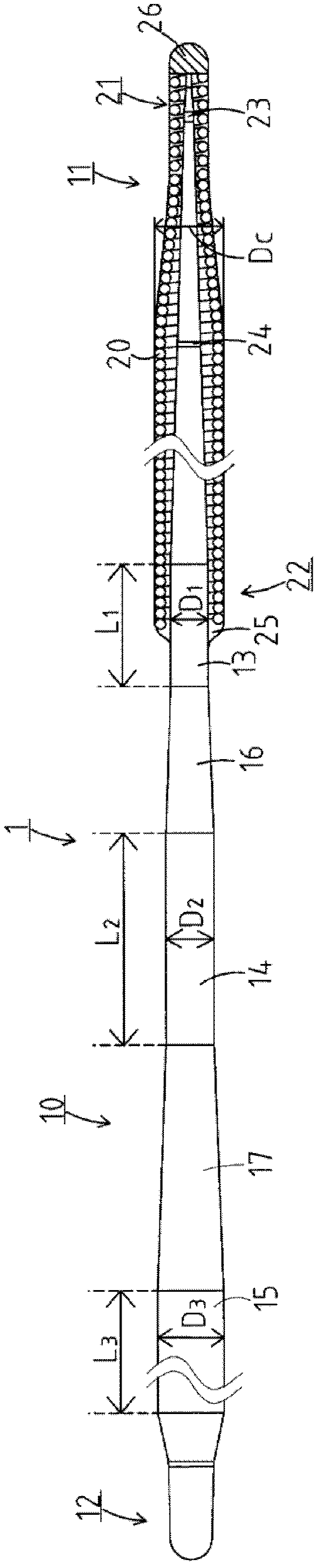
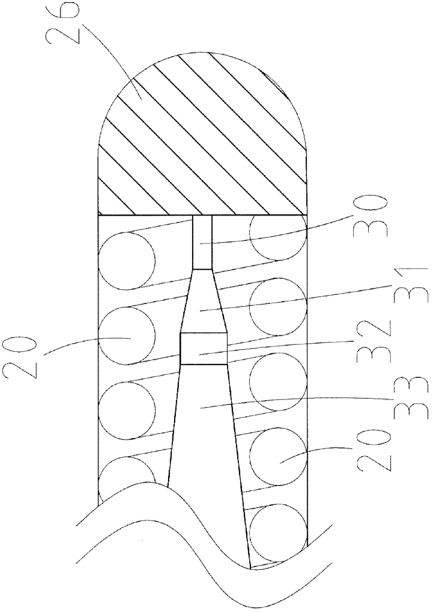
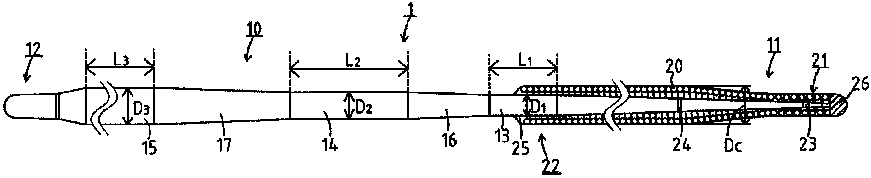
[0053] figure 1 The lead wire 1 of the present embodiment shown includes: a mandrel 10 having a first front end portion 11 and a first rear end portion 12 located on the opposite side of the first front end portion 11; and a coil body 20 having a second front end portion 21 and The second rear end portion 22 is located on the opposite side of the second front end portion 21 , and the coil body 20 is wound on the outer periphery of the first front end portion 11 of the mandrel 10 .

[0054]The mandrel 10 includes: a f...


PUM

PropertyMeasurementUnit
lengthaaaaaaaaaa
lengthaaaaaaaaaa
lengthaaaaaaaaaa

Abstract

A guidewire includes a core shaft having a first tip portion and a first rear end portion, and a coiled body having a second tip portion and a second rear end portion and wound around the outer circumferential surface of the first tip portion. The core shaft further includes a first cylindrical portion, a second cylindrical portion, and a third cylindrical portion. The second cylindrical portion has an outer diameter larger than an outer diameter of the first cylindrical portion and smaller than the maximum diameter of the coiled body, and the third cylindrical portion has an outer diameter larger than an outer diameter of the second cylindrical portion and smaller than the maximum diameter of the coiled body.

Description

technical field [0001] The invention relates to a wire. Background technique [0002] Conventionally, guide wires for guiding devices such as balloons and stents to lesion areas are known as one of medical devices used in percutaneous coronary angioplasty (hereinafter also referred to as PCI). [0003] For example, Patent Document 1 (Japanese Patent Laid-Open Publication No. Hei 4-309368) discloses such a lead wire. The lead wire is composed of a mandrel and a coil body, the mandrel has a cylindrical base end portion and a tapered front end portion connected to the base end portion, and the coil body is wound around the outer periphery of the front end portion , and the mandrel and the coil body are welded together at a specified position. [0004] In addition, in the guide wire described above, the distal end side of the mandrel is the distal end portion of the guide wire, and the base end side of the mandrel is the proximal end portion of the guide wire. The distal end ...

Claims


Application Information

Patent Timeline
Patent Type & Authority Applications(China)
IPC IPC(8): A61M25/09
CPCA61M2025/09175A61M2025/0915A61M25/09A61M2025/09075Y10T29/49826
Inventor 西岸诚
Owner ASAHI INTECC CO LTD
Why Eureka
Try Eureka