Vertical column structure of numerical control floor-type boring and milling machine

A boring and milling machine and column technology, which is applied in the field of column structure, can solve the problems of thermal deformation and insufficient rigidity, and achieve the effect of strong rigidity and not easy thermal deformation

Inactive Publication Date: 2012-08-01
武义机床制造有限公司
View PDF4 Cites 3 Cited by
  • Summary
  • Abstract
  • Description
  • Claims
  • Application Information

AI Technical Summary

Problems solved by technology

[0003] The purpose of the present invention is to solve the lack of rigidity and thermal deformation of the column structure of the existing floor boring and milling machine, and provide a column structure of the CNC floor boring and milling machine that can improve the overall rigidity and reduce the thermal deformation of the machine tool during operation

Method used


Image

  • Vertical column structure of numerical control floor-type boring and milling machine
  • Vertical column structure of numerical control floor-type boring and milling machine
  • Vertical column structure of numerical control floor-type boring and milling machine

Examples


Embodiment Construction

[0010] The present invention will be further described below in conjunction with embodiment.

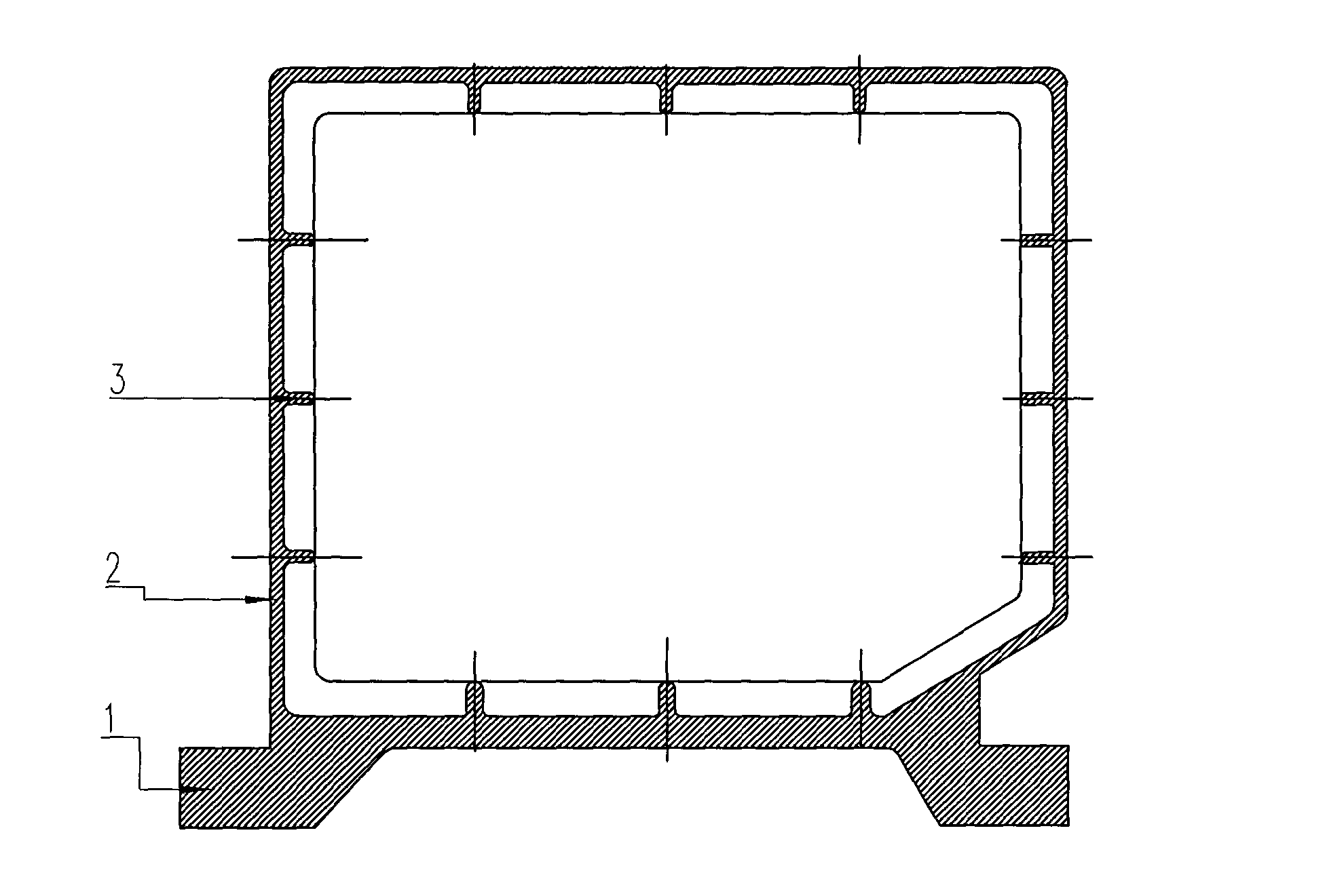
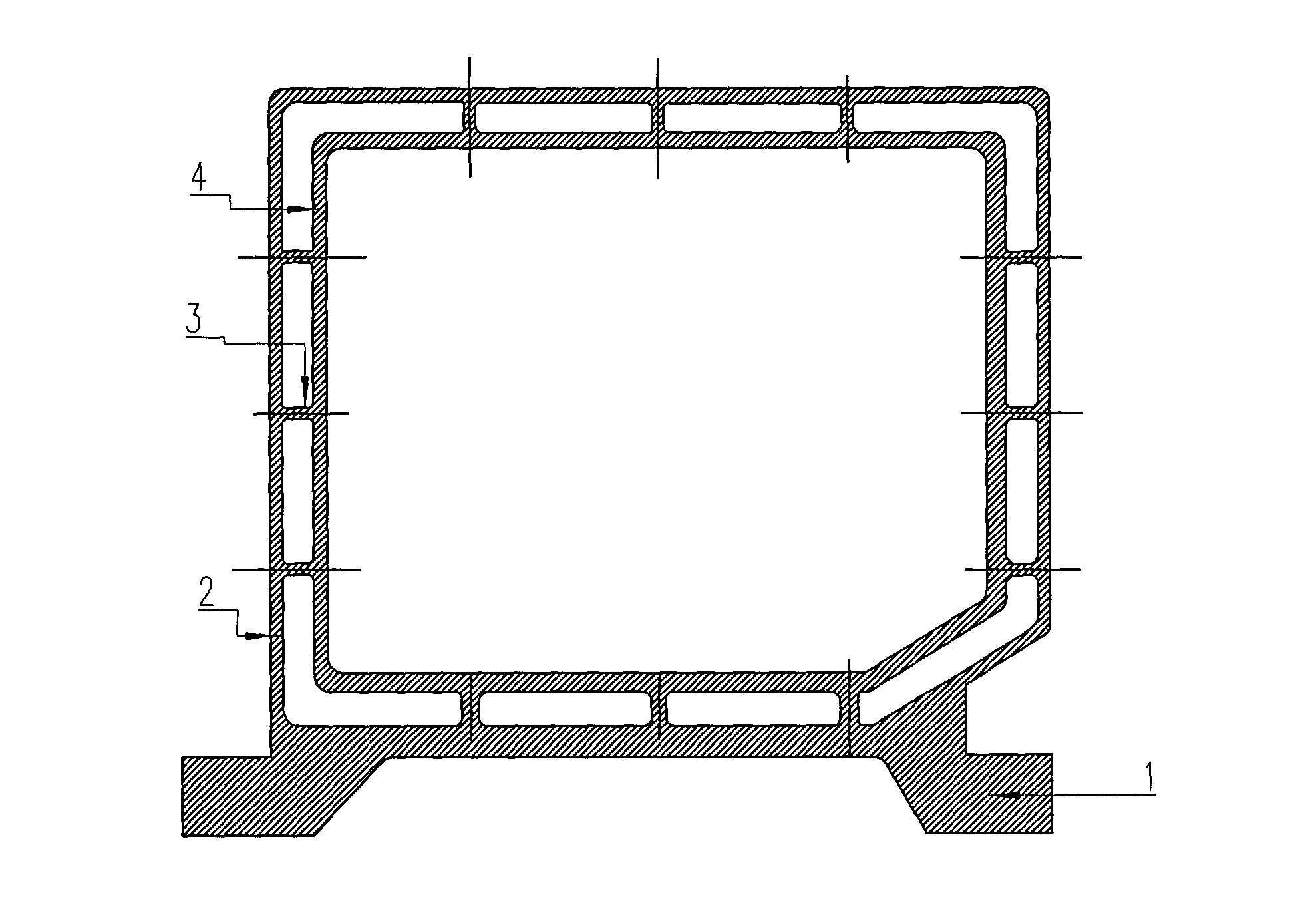
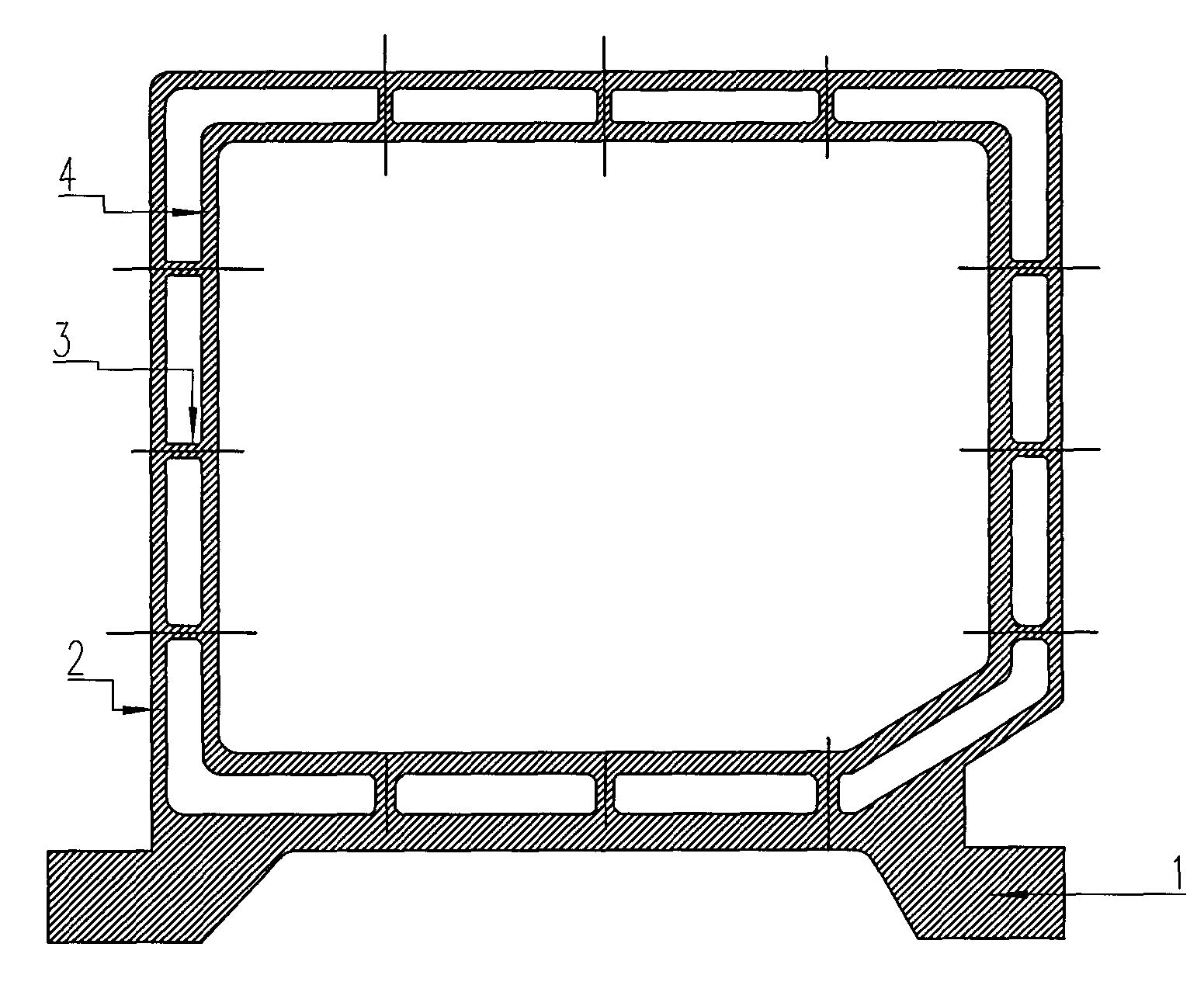
[0011] Refer to attached figure 2 , a column structure of a CNC ground boring and milling machine, including a column body 1, a wall plate 2 and a rib plate 3, and also includes an inner wall plate 4, the inner wall plate is arranged parallel to the wall plate, and one end of the rib plate is connected to the wall plate , and the other end is connected to the inner wall panel. The rib plate is integrally formed with the wall plate and the inner wall plate.


PUM


Abstract

A vertical column structure of a numerical control floor-type boring and milling machine comprises a vertical column body, a wall plate, a rib plate and an inner wall plate parallel to the wall plate. One end of the rib plate is connected with the wall plate, and the other end of the rib plate is connected with the inner wall plate. With the double wall plates and 'latticed' ribs, the vertical column structure is domestically initiated, is high in rigidity, is not easy to generate heat deformation when the machine runs, and cannot affect geometric accuracy of the machine.

Description

(1) Technical field [0001] The invention relates to a column structure of a numerical control floor boring and milling machine. (2) Background technology [0002] The CNC floor boring and milling machine is a heavy-duty machine tool with a wide range of uses. Indispensable equipment in these fields, and plays an irreplaceable role for other machine tools in these fields. The column is an important part of a large CNC floor boring and milling machine. The movement of the spindle in the X direction depends on the column, and the movement of the spindle in the Y direction is the up and down movement of the ram on the column. Whether the rigidity of the whole machine tool is good or not depends on the design of the column. its own rigidity. In the past, the design of the column consisted of a single-layer stiffened plate structure. Considering the casting process of the column, the thickness of the wall plate for such a large casting as the column should not be less than 30mm,...

Claims


Application Information

Patent Timeline
Patent Type & Authority Applications(China)
IPC IPC(8): B23Q1/01
Inventor 陈广寨陈勇良童德旺
Owner 武义机床制造有限公司
Why Eureka
Try Eureka