Flat plate integral type solar drier

A flat-panel solar energy, integrated technology, applied in the direction of solar thermal power generation, solar thermal devices, dry gas arrangement, etc., can solve the problems of product quality decline, high cost, low solar energy utilization rate, etc.

Inactive Publication Date: 2012-08-01
ZHENJIANG XINMENGXI ENERGY TECH
View PDF7 Cites 1 Cited by
  • Summary
  • Abstract
  • Description
  • Claims
  • Application Information

AI Technical Summary

Problems solved by technology

[0002] In the field of crop drying, the common drying heat sources are mostly coal or oil heating, and the temperature of the hot air is around 200°C, which will easily lead to a

Method used


Image

  • Flat plate integral type solar drier
  • Flat plate integral type solar drier

Examples


Embodiment Construction

[0011] The embodiments of the present invention will be further described below in conjunction with the accompanying drawings.

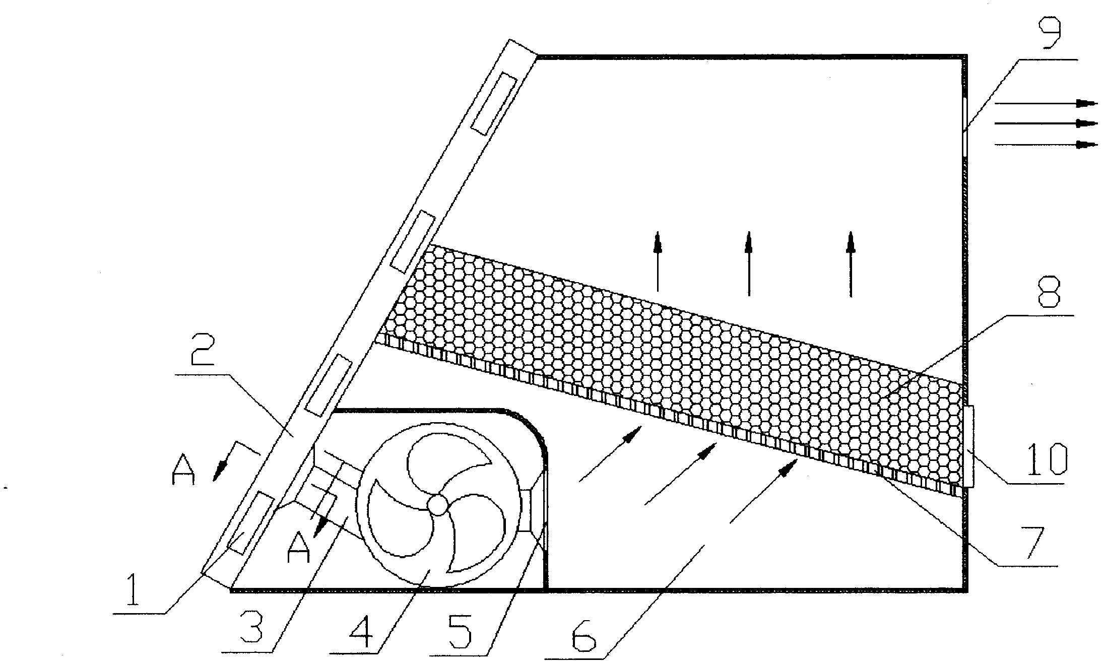
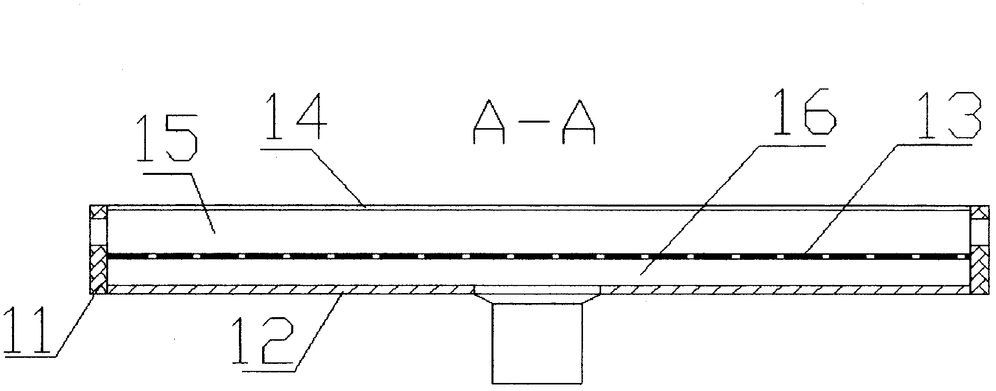
[0012] The device uses a porous flat solar air heat collector 2 as a heat source. After the fan 4 is started, the hot air is extracted from the porous flat solar air heat collector 2 and sent into the drying bin to dry the goods. The outside air enters the collector front chamber 15 from the air inlets 2 evenly distributed on both sides of the porous flat solar air heat collector 2, and enters the collector rear chamber 16 after passing through the small holes on the porous heat collector plate 13 to absorb heat. Finally, it enters the fan 4 from the outlet of the heat collector through the air outlet valve of the heat collector. The hot air first enters the pressure equalization chamber 6 of the drying bin through the action of the fan 4, and then passes through the perforated sieve 7 and the dry matter 8, and the moisture is discharged from the ai...


PUM


Abstract

The invention discloses a flat pipe integral type solar drier, which comprises a solar heat collector, a blower, a ventilating pipeline and a drying chamber. Heat collection plates of the heat collector are multi-hole heat collection plates, and a perforated sieve of the drying chamber is placed at an inclination angle of 20 degrees. The drying temperature of the system is around 30-50 DEG C, so that the quality of dried products is ensured. In addition, the air heat collector and the drying chamber constitute a whole with a compact structure, and the flat pipe integral type solar drier reduces heat loss and is suitable for crop drying quantity demanded by a single rural family.

Description

1. Technical field [0001] The invention relates to solar heat utilization technology and crop drying technology, in particular to a solar dryer which combines a porous flat solar air heat collector and a drying chamber into a whole. 2. Background technology [0002] In the field of crop drying, most common drying heat sources are coal or oil heating, and the temperature of the hot air is around 200°C, which may easily lead to a decline in product quality. [0003] There are many patents about solar dryers at present, but due to reasons such as low utilization rate of solar energy and high cost, they still need to be popularized. A few existing related patents are listed below: [0004] The patent "rapid high-temperature solar dryer" (application number: 200620057287.2) proposes a solar dryer, the heat collecting part of which is a heat collecting plate, the air flows through the channel between the plate and the transparent cover to absorb heat, and enters the drying device...

Claims


Application Information

Patent Timeline
IPC IPC(8): F26B21/00F24J2/46F24J2/50
CPCY02B10/20Y02E10/40
Inventor 王金平
Owner ZHENJIANG XINMENGXI ENERGY TECH
Why Eureka
Try Eureka