Mixed-light-source liquid-crystal projection light engine system

A technology of liquid crystal projection and mixed light source, applied in the field of projection display system, can solve the problems of low output measurement, increased optical etendue of light source, and high cost, and achieve the advantages of improving output brightness, reducing speckle phenomenon and ensuring safety. Effect

Inactive Publication Date: 2012-08-01
杭州研明光电技术有限公司
View PDF10 Cites 24 Cited by
  • Summary
  • Abstract
  • Description
  • Claims
  • Application Information

AI Technical Summary

Benefits of technology

This technology uses two types of lights - white or yellow for better color quality when combined with an invisible blue-green wavelength from one type of lamp called Lamp Red). By combining these three colors together they create more vibrant colored images on paper without any visible streaks like those seen during traditional methods such as painting. Additionally, this combination also improves overall efficiency compared to just mixing different materials altogether.

Problems solved by technology

This patented describes how advanced semiaxpersion liquid crystals (LC), particularly those made from gallium nitride (GaN). These materials exhibit excellent properties like narrow emission spectrum, broad absorption spectra, linear dichroism, circularly polarizing property, and minimal cross talk between multiple components. They allow for better control of emitted light intensity and reduce noise levels during display. Additionally, they enable longer lifetime of displays through combining different colored lights together within one package instead of individually controlling them separately. Overall, these advancements help create safer and faster electronic products.

Method used


Image

  • Mixed-light-source liquid-crystal projection light engine system
  • Mixed-light-source liquid-crystal projection light engine system
  • Mixed-light-source liquid-crystal projection light engine system

Examples


Embodiment 1

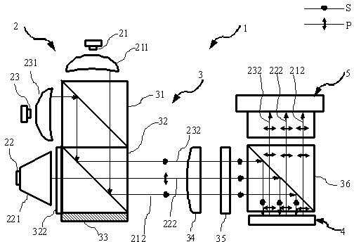
[0038] figure 1 The first embodiment of the reflective liquid crystal projection display system 1 using mixed light sources of the present invention is given, including a light source module 2 , a polarized light management module 3 , an image information module 4 and a projection lens 5 .

[0039] The light source module 2 includes a red laser 21, a blue laser 23, a green LED 22, a red laser beam expander and shaper 211, a blue laser beam expander and shaper 231 and a green light homogenizer 221, and the red laser 21 and the red laser beam expander and shaper 211, the blue laser 23 is connected to the blue laser beam expander and shaper 231, and the green LED 22 is connected to the green homogenizer 221.

[0040] The polarized light emitted by the red laser 21 and the blue laser 23 passes through the red laser beam expander and shaper 211 and the blue laser beam expander and shaper 231 respectively, and then becomes a rectangular beam required for illumination. The natural l...

Embodiment 2

[0052] Figure 4 A second embodiment of the present invention is given. In the second embodiment, the red laser 21 and the blue laser 23 are packaged together to form a red and blue laser 26 . The red light and the blue light emitted by the red and blue laser 26 directly generate common path light with the same polarization state, without the dichroic prism 31 for color combination. Compared with the first example, this example can significantly reduce the volume of the whole machine and reduce components such as dichroic mirrors, which is beneficial to the miniaturization of the projection system.

[0053] Figure 5 The ray trajectories and polarization states of the red light and blue light in the second embodiment are given. The red light 212 and the blue light 232 emitted by the red and blue laser 26 are incident on the first PBS 32 after passing through the red and blue laser beam expander and shaper 234 . Since the red and blue laser 26 produces highly polarized S li...

Embodiment 3

[0056] Figure 7 A third embodiment of the present invention is given. Compared with the first embodiment, the difference of this embodiment is that the light source module 2 consists of blue lasers 23 and 25, a blue beam expander and shaper 231, a transparent blue anti-green filter 323, a green phosphor plate 223, The green beam expander and shaper 224, the red LED 24 and the red homogenizer 241 are composed to provide mixed three-primary-color illumination for the system. The polarization color combining unit is composed of a dichroic prism 31 , a first PBS 32 , a mirror 33 , a quarter-wave plate 321 for red light, and a quarter-wave plate 322 for green light.

[0057] The dichroic prism 31 synthesizes the light emitted by the red LED 21 and the blue laser 23 into a common beam, and a red quarter-wave plate 321 is glued on the side of the dichroic prism 31 corresponding to the red LED. The first PBS 32 is glued together with the dichroic prism 31 , and a quarter 322 of gre...


PUM


Abstract

The invention provides a mixed-light-source liquid-crystal projection light engine system. The portable liquid-crystal projection light engine system is composed of a light source module, a polarized light management module, an image signal module and a projection lens, wherein the light source module consists of a high-brightness laser, an incoherent LED (Light-Emitting Diode) solid light source, a fluorescent device and the like. The output brightness of the projection system is greatly increased, the light source module is safe and environmentally friendly, and projected images have bright color and clear quality. The polarized light management module consists of a color-combining prism, a polarization beam splitter (PBS), a polarization color-combining device and the like, and different polarization states of three-primary-color mixed light are integrated into the same polarized light to be emitted to the image signal module. The image signal module is a monolithic reflection type liquid crystal light modulation device, and image signals are loaded to the three-primary-color polarized light in sequence according to the image signals corresponding to primary colors. The projection lens is used for projecting the light carrying the image signals onto a screen.

Description


Claims


Application Information

Patent Timeline
Owner 杭州研明光电技术有限公司
Why Eureka
Try Eureka