Rectifier bridge arm

A rectifier bridge, a pair of technology, applied in the direction of semiconductor/solid-state device components, semiconductor devices, electrical components, etc., to achieve the effect of improving efficiency, eliminating branch impedance differences, and reducing power loss

Active Publication Date: 2014-01-15
HUAZHONG UNIV OF SCI & TECH
View PDF5 Cites 0 Cited by
  • Summary
  • Abstract
  • Description
  • Claims
  • Application Information

AI Technical Summary

Problems solved by technology

[0005] The technical problem to be solved by the present invention is to provide a rectifier bridge arm for the current-sharing defect of the parallel branch in the current high-current rectifier, which can fundamentally reduce the problem of unbalanced impedance between the branches and improve the performance of the rectifier power supply equipment

Method used


Image

  • Rectifier bridge arm
  • Rectifier bridge arm
  • Rectifier bridge arm

Examples


Embodiment Construction

[0022] The present invention will be further explained and illustrated below in conjunction with the embodiments and accompanying drawings.

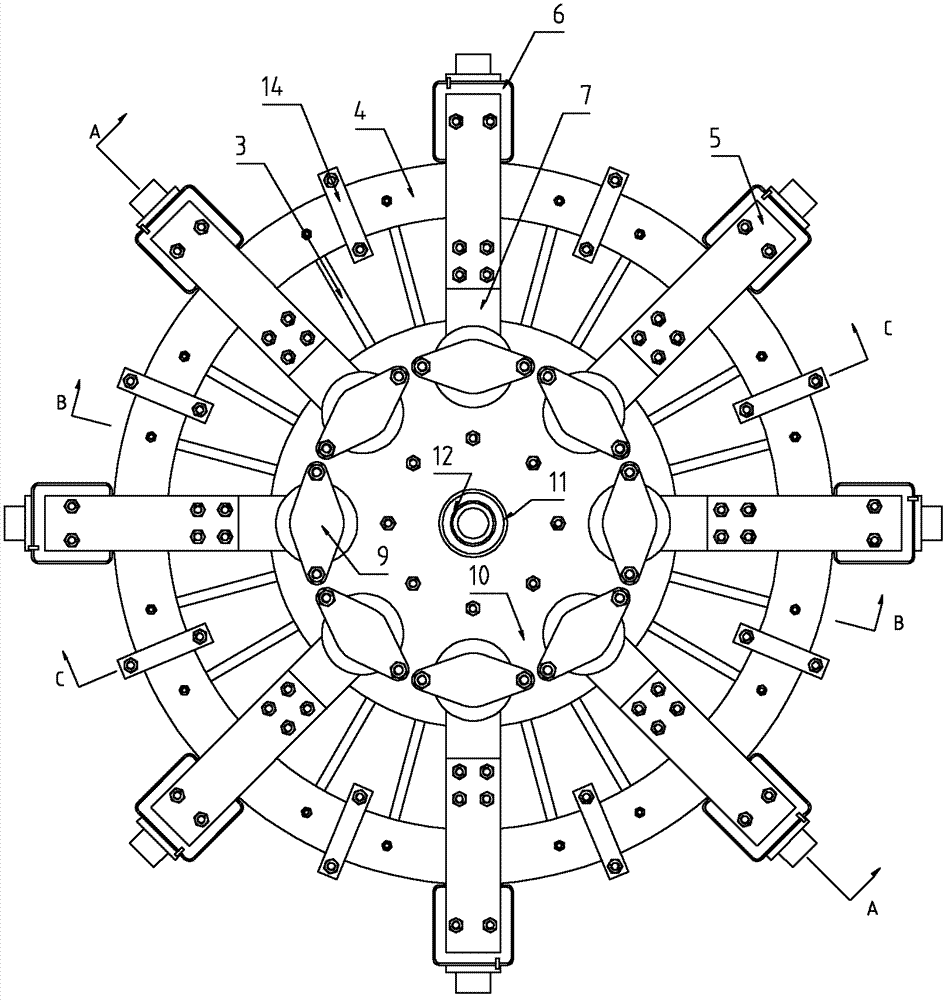
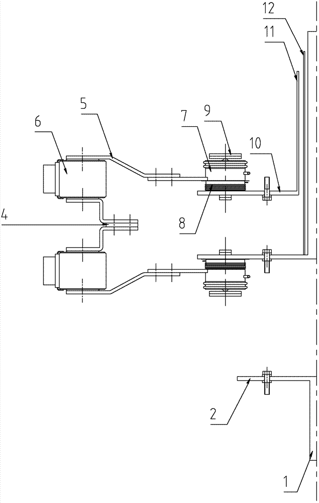
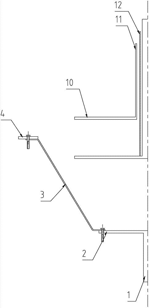
[0023] Such as figure 1 and 2 As shown, the rectifier bridge arm of the present invention includes an AC incoming line column 1, a pair of AC pole plates 2, a plurality of AC connecting bars 3, an AC bus bar 4, a plurality of DC connecting bars 5, a plurality of fast fuses 6, and a plurality of A heat sink 7, a plurality of semiconductor switching devices 8, a plurality of crimping fixtures 9, a pair of DC plates 10 and a pair of DC outlet posts 11.

[0024] Such as figure 1 As shown, the AC busbar 4 is ring-shaped, the DC pole plate 10 and the AC pole plate 2 are circular, the AC busbar 4 is arranged outside the DC pole plate 10, the DC outlet column 11 is arranged in the center of the DC pole plate 10, and the crimping fixture 9 are evenly distributed along the circumferential direction, the fast fuses 6 are evenly distributed along...


PUM


Abstract

The invention discloses a rectifier bridge arm, which comprises an alternating-current (AC) inlet terminal, a pair of AC polar plates, a plurality of AC connecting bars, an AC bus bar, a plurality of direct-current (DC) connecting bars, a plurality of rapid fuses, a plurality of heat radiators, a plurality of semiconductor switching devices, a plurality of crimping clamps, a pair of DC polar plates and a pair of DC outlet terminals. The AC inlet terminal is arranged at the center of the AC polar plates and are fixedly connected with the AC polar plates; the AC bus bar is arranged at the outer part of the DC polar plates and is connected with the AC polar plates through the AC connecting bars; one end of each rapid fuse is connected with the AC bus bar, and the other end of each rapid fuse is connected with the heat radiators through the DC connecting bars; the heat radiators and the semiconductor switching devices are evenly mounted on the DC polar plates along the circumferential direction through the crimping clamps; the DC outlet terminals are arranged at the centers of the DC polar plates and are fixedly connected with the DC polar plates; the AC bus bar is annular; and the DC polar plates and the AC polar plates are circular. According to the rectifier bridge arm, the problem of unbalanced impedance among branches is solved, and the performance of rectifier power supply equipment is improved.

Description

technical field [0001] The invention relates to the technical field of rectifying power supplies, in particular to a rectifying bridge arm. Background technique [0002] The rectifier bridge arm is the basic functional structure in modern rectifier power supply equipment, usually composed of two groups of semiconductor switching elements (such as diodes, thyristors, etc.) connected through bus bars. Combining multiple rectifier bridge arms according to different topological structures can form a rectifier power supply with different functions and characteristics. [0003] DC power supplies ranging from tens to hundreds of kiloamperes are often used in industrial production such as electrolysis and chemical industry, and the rectification part requires a large number of parallel switching elements to increase capacity. In terms of mechanical design, the connecting row between the switching element and the main busbar is generally equal in length, but due to the different ins...

Claims


Application Information

Patent Timeline
Patent Type & Authority Patents(China)
IPC IPC(8): H01L25/07H01L23/367
CPCH01L2924/0002
Inventor 张明何泱
Owner HUAZHONG UNIV OF SCI & TECH
Why Eureka
Try Eureka