
A liquid crystal display panel with repair line structure

A liquid crystal display panel and repair line technology, which is applied in nonlinear optics, instruments, optics, etc., can solve the problems of increasing the impedance of the repair line and the large difference in the impedance of the repair line.

Active Publication Date: 2017-03-22
NANJING CEC PANDA LCD TECH
View PDF6 Cites 0 Cited by
  • Summary
  • Abstract
  • Description
  • Claims
  • Application Information

AI Technical Summary

Problems solved by technology

[0005] Use the above method to avoid interference with the pattern of the non-display area, but the extra distance and contact impedance through the COF line structure greatly increase the impedance of the repair line, resulting in a large difference in impedance from the repair line on the other side

Method used


Image

  • A liquid crystal display panel with repair line structure
  • A liquid crystal display panel with repair line structure
  • A liquid crystal display panel with repair line structure

Examples


Embodiment Construction

[0020] Below in conjunction with accompanying drawing and specific embodiment, further illustrate the present invention, should be understood that these embodiments are only for illustrating the present invention and are not intended to limit the scope of the present invention, after having read the present invention, those skilled in the art will understand various aspects of the present invention Modifications in equivalent forms all fall within the scope defined by the appended claims of this application.

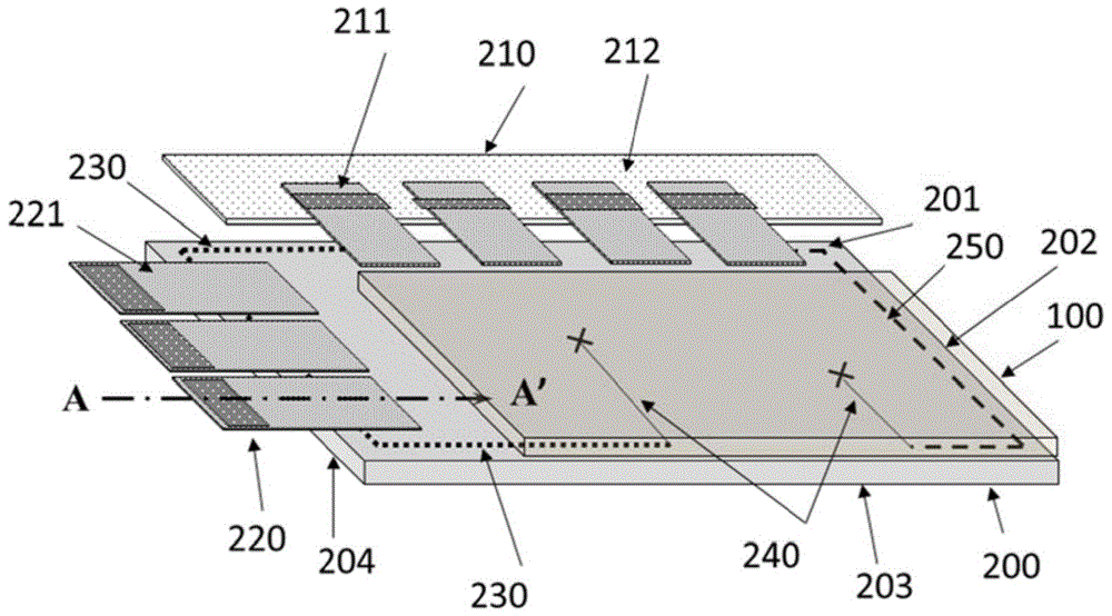
[0021] image 3 It is a structural schematic diagram of a liquid crystal display panel with repair lines. The liquid crystal display panel includes a color filter substrate 100 and an array substrate 200 disposed opposite to each other, a pixel array, source drive units 210 and gate electrodes connected to adjacent sides of the array substrate 200 drive unit 220 . Both the color filter substrate 100 and the array substrate 200 include a display area and a non-display ar...


PUM


Abstract

The invention provides a liquid crystal display panel with a repair wire structure. A first side edge and a fourth side edge of an array substrate are respectively connected with a source electrode driving unit and a grid electrode driving unit, the source electrode driving unit and the grid electrode driving unit are respectively provided with a plurality of source electrode crystal coated thin films and a plurality of grid electrode crystal coated thin films connected with a non-display region of the array substrate, the fourth side edge of the array substrate is provided with a plurality of first repair wires, a second side edge of the array substrate is provided with a plurality of second repair wires, one end of each of the first repair wires is connected with one of the source electrode crystal coated thin films, and the first repair wires pass through the bottoms of the grid electrode crystal coated thin films to be correspondingly connected to data wires arranged at a third side edge. The liquid crystal display panel has the advantages that the repair wires are directly arranged on the array substrate, and the impedance is integrally reduced in modes of reducing the thread and reducing the contact impedance, so that load impedances of the repair wires of the left and right non-display regions of the array substrate tend to be consistent.

Description

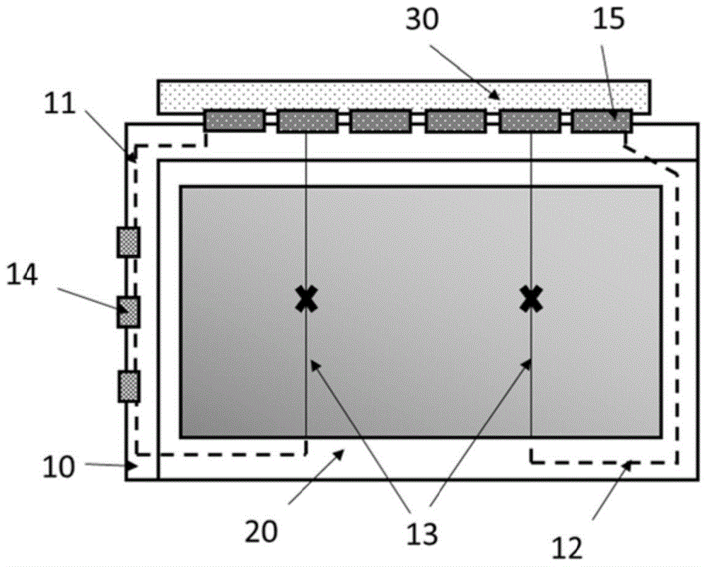
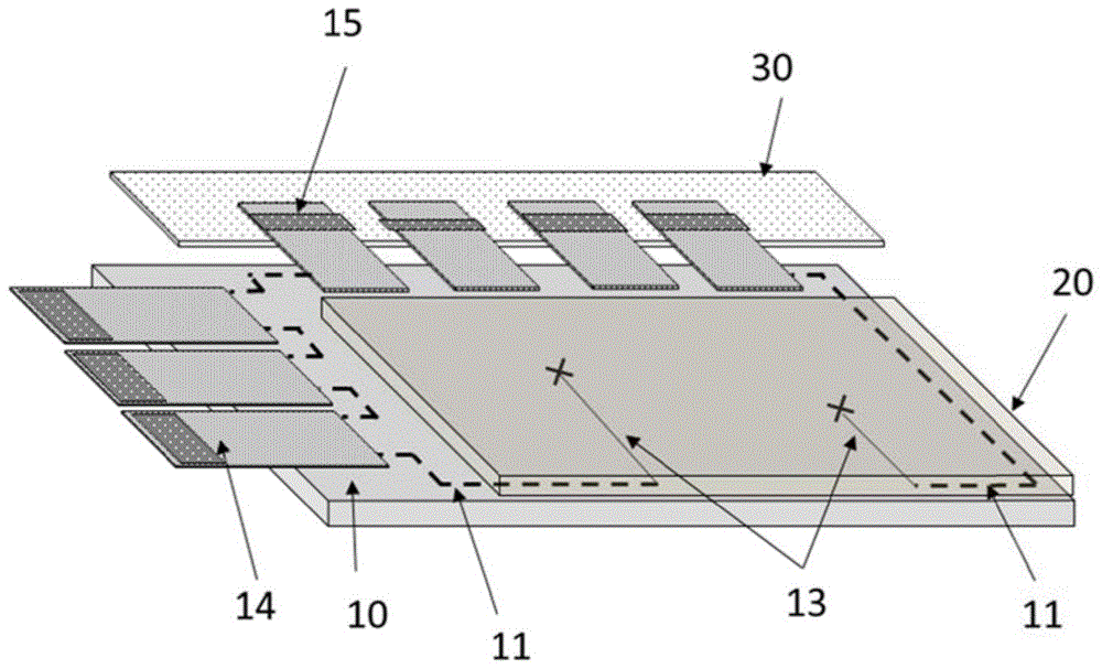
technical field [0001] The invention relates to a liquid crystal display panel with a repair line structure in the manufacturing process of the liquid crystal display panel. Background technique [0002] During the manufacturing process of the TFT substrate of the liquid crystal display panel, the display of the substrate is poor due to various reasons. The more serious one is the line defect. There are two main repair methods for the broken line defect, one is the repair method in the screen, and the other is One is the off-screen repair method. [0003] Off-screen repair, that is, by designing off-screen wiring, the signal is directed from other paths to the truncated line. The path of the repair line starts from the Source side, passes through the non-display area on both sides of the substrate, and finally connects to the anti-Source side, such as figure 1 and figure 2 As shown, the array substrate 10 is attached to the color filter substrate 20, and the non-display ...

Claims


Application Information

Patent Timeline
Patent Type & Authority Patents(China)
IPC IPC(8): G02F1/13
Inventor 刘文雄王鸣昕
Owner NANJING CEC PANDA LCD TECH
Learn More