Bidirectional energy flowing flow battery energy storage grid connection device and control method thereof

A liquid flow battery and two-way flow technology, which is applied in the direction of battery circuit devices, circuit devices, harmonic reduction devices, etc., can solve the problem of complex switching frequency, capacity and coordination of DC-DC and DC-AC links, switching modulation strategies and control strategy complexity, system efficiency reduction and other issues

Active Publication Date: 2012-08-01
HUAZHONG UNIV OF SCI & TECH
View PDF4 Cites 13 Cited by
  • Summary
  • Abstract
  • Description
  • Claims
  • Application Information

AI Technical Summary

Problems solved by technology

This structure requires pre-charging when the energy storage module is used for the first time, so it is necessary to add a pre-charging auxiliary device, and the structure is complicated; 2. The structure of PWM rectifier plus DC-DC converter
With more DC-DC links, the efficiency of the entire system is reduced, and the switching frequency, capacity and coordination of the DC-DC and DC-AC links are complicated; 3. The structure of the cascaded H-bridge AC-DC converter
The switch modulation strategy and control strategy are relatively complex, and at the same time, it is necessary to deal with the imbalance control problem between each group of flow batteries

Method used


Image

  • Bidirectional energy flowing flow battery energy storage grid connection device and control method thereof
  • Bidirectional energy flowing flow battery energy storage grid connection device and control method thereof
  • Bidirectional energy flowing flow battery energy storage grid connection device and control method thereof

Examples


example

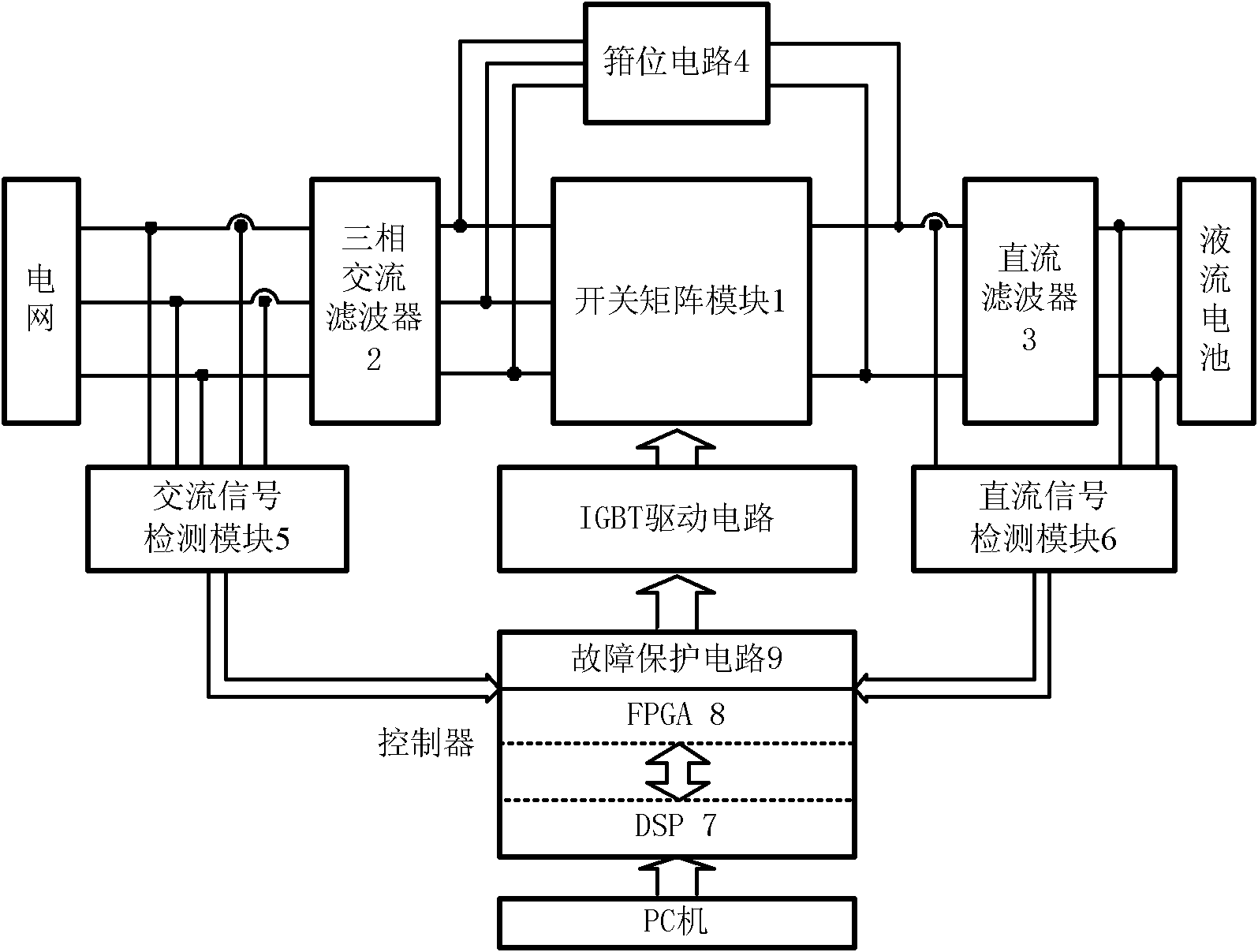
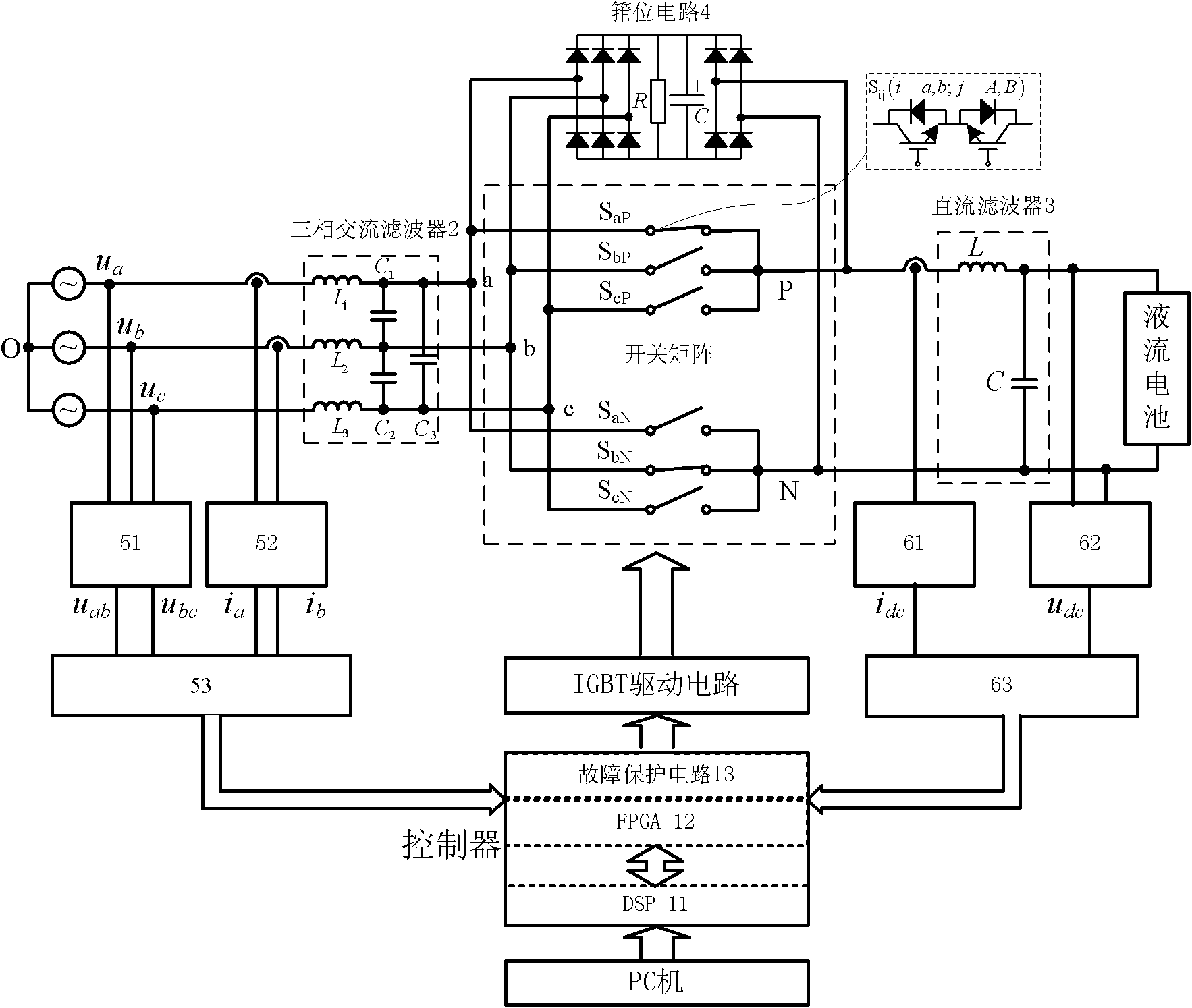
[0050] Such as figure 2 As shown, the switch matrix module 1 is composed of six bidirectional power switches. where S i,j (i=P, N; j=a, b, c three-phase) represents a bidirectional power switch, each bidirectional power switch is composed of two insulated gate bipolar transistors (IGBTs) with antiparallel diodes using "common emitter "Structure composition. The output terminals of the three bidirectional power switches of the upper bridge arm are connected together to form an output terminal P, and the output terminals of the three bidirectional power switches of the lower bridge arm are connected together to form an output terminal N, and finally output a DC voltage U PN . The input side of the matrix three-phase AC-DC converter is the three-phase grid voltage, respectively with u a , u b , u c express. There is a three-phase AC filter 2 indirectly between the matrix three-phase AC-DC converter and the grid. A DC filter 3 is connected to the output side of the matrix...


PUM


Abstract

The invention discloses a bidirectional energy flowing flow battery energy storage grid connection device and a control method thereof. The device comprises a matrix type three-phase alternating current-direct current converter, a signal detection module, an insulated gate bipolar transistor (IGBT) driving circuit and a controller, wherein the matrix type three-phase alternating current-direct current converter comprises a switch matrix module, a three-phase alternating current filter, a direct current filter and a clamping circuit; and the signal detection module comprises an alternating current signal detection module and a direct current signal detection module. Due to the adoption of the matrix type three-phase alternating current-direct current converter, a power factor is high, energy can bidirectionally flow, a wide direct current voltage output range is adjustable, the device can be used for the charging of a flow battery as well as the deep discharge of the flow battery, and the effective utilization rate of electric energy is increased. An alternating current side power factor and a harmonic distortion factor are regulated under the control of the controller, so that the conditions of the power factor and harmonics of a power grid side can be known. Due to the adoption of digital signal processor (DSP) and field programmable gate array (FPGA) control modes, the device is simple in structure, the response of a system is quickened, and the reliability of the system is improved.

Description

technical field [0001] The invention belongs to the technical field of power electronic conversion devices, and relates to a liquid flow battery energy storage power electronic grid-connected device with bidirectional energy flow and a control method thereof. The device is based on a direct three-phase alternating current (AC) to direct current ( DC) matrix converter device to realize the deep charge and discharge work of the flow battery energy storage system, simplify the system structure and improve the utilization efficiency of the power grid. Background technique [0002] Energy storage technology has been regarded as an important part of the grid operation process. After the energy storage link is introduced into the system, it can effectively realize the demand side management, eliminate the peak-valley difference between day and night, and smooth the load, which can not only make more effective use of power equipment, reduce power supply costs, but also promote the a...

Claims


Application Information

Patent Timeline
Patent Type & Authority Applications(China)
IPC IPC(8): H02J3/32H02J3/18H02J3/01H02J7/02
CPCY02E40/30Y02E40/40
Inventor 林桦冯波王兴伟安星胡三影
Owner HUAZHONG UNIV OF SCI & TECH
Why Eureka
Try Eureka