Rice planter
A technology of rice transplanter and rice, which is applied in the direction of transplanting machinery, agriculture, application, etc., can solve the problems that operators cannot distinguish, and achieve the effect of simple structure, reduced manufacturing cost and high manufacturing cost
- Summary
- Abstract
- Description
- Claims
- Application Information
AI Technical Summary
Problems solved by technology
Method used
Image

Examples
Example Embodiment
[0068] Embodiment 1
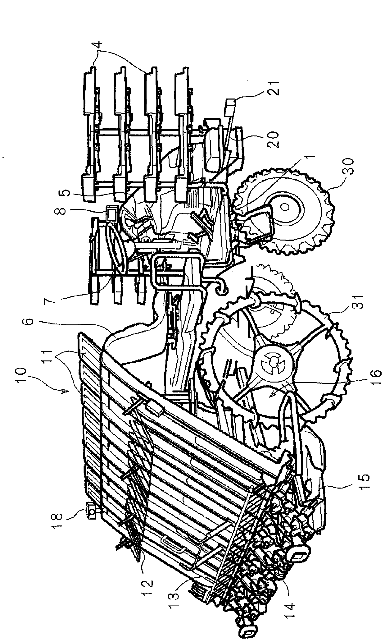
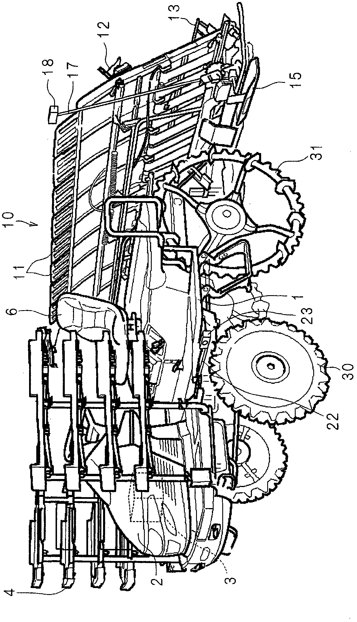
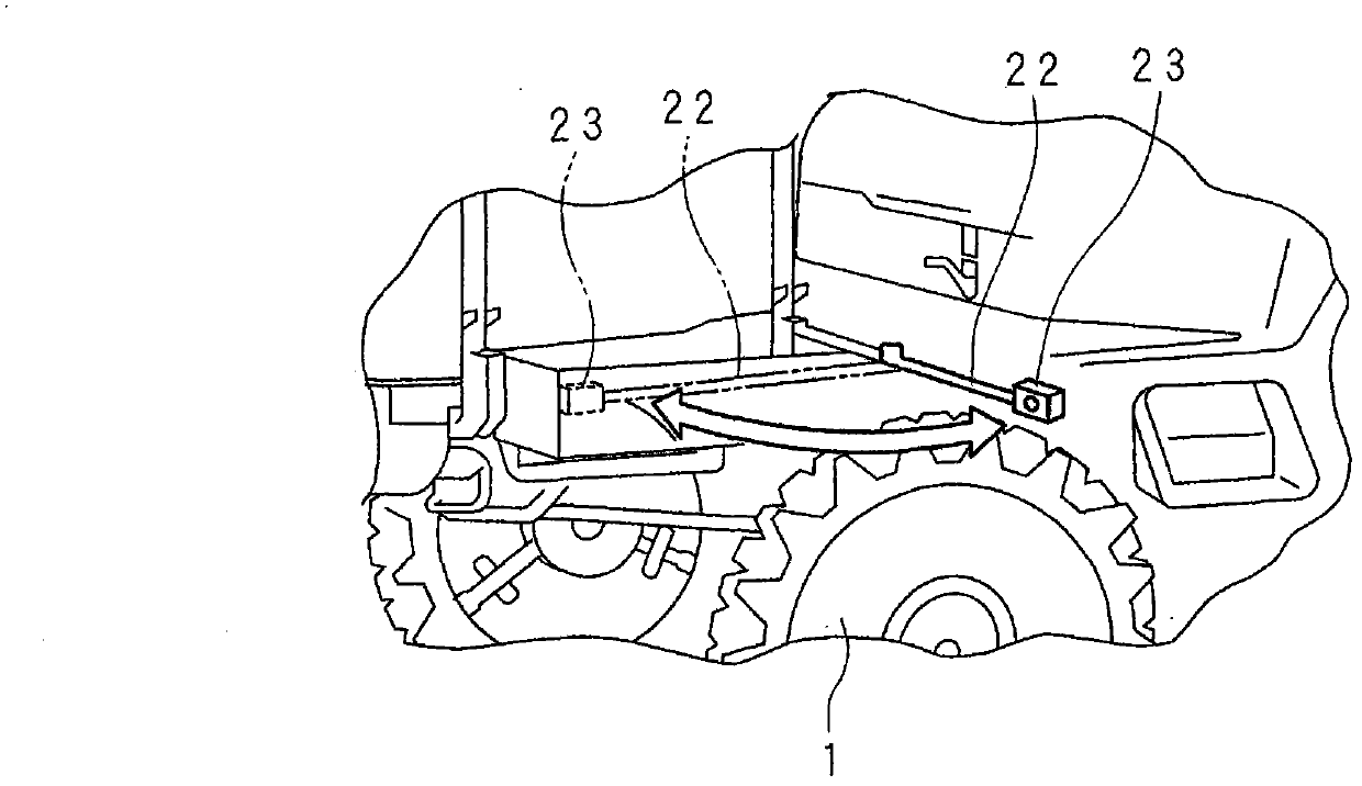
[0069] Hereinafter, the present invention will be described in detail based on the schematic diagram of the rice transplanter of the first embodiment. figure 1 是,shows a simplified three-dimensional view of the rice transplanter viewed from the rear right; figure 2 是,shows a simplified three-dimensional view of the rice transplanter viewed from the left front; image 3 A schematic perspective view of the arm.
[0070] The rice transplanter includes a running part 1 having a chassis, a hood 2 is provided at the front of the running part 1, and an engine 3 is provided inside the hood 2. A transmission mechanism for transmitting the driving force of the engine 3 and a front sleeve (not shown) in which a suspension and the like are built-in are provided on the lower side of the front portion of the traveling unit 1, and the front wheel 30 is supported by the front axle. A transmission mechanism for transmitting the driving force of the engine 3 and a rear sleeve ...
Example Embodiment
[0103] Embodiment 2
[0104] Hereinafter, the present invention will be described in detail based on the drawings showing the rice transplanter of the second embodiment. Figure 17 It is a schematic exploded perspective view showing the structure near the steering wheel 7.
[0105] Such as Figure 17 As shown, the steering wheel 7 is connected to the upper end of the steering shaft 70 arranged in the up-down direction through a column bush 71 and a shaft bush 72. A magnet is provided on the outer peripheral surface of the steering shaft 70, and a rotation angle sensor 73 that detects the rotation angle of the steering shaft 70 is provided around the middle portion of the steering shaft 70. The rotation angle sensor 73 has a unit that detects the position around the axis of the steering shaft 70, such as a Hall element or a magnetic sensor.
[0106] Figure 18 It is a schematic block diagram showing the surrounding structure of the controller 90. The detection value of the rotation ...
Example Embodiment
[0112] Embodiment 3
[0113] Hereinafter, the present invention will be described in detail based on the drawings showing the rice transplanter of the third embodiment. Figure 21 It is a schematic diagram showing an example of an image of a seedling field place where seedlings are being transplanted at present and a place adjacent to the place where seedlings are planted later.
[0114] The right front camera 21 and the left front camera 23 of the rice transplanter of Embodiment 3 need to use a wide-angle lens corresponding to the long-distance line. Figure 21 It means that the display section 8 of the seedling field photographed by the front right camera 21 is displayed, and the curved line 100 corresponding to the tilt of the image using the wide-angle lens is displayed on the right. In addition, the furrow 130 is displayed at the left end of the display unit 8, and the furrow 130 is shown with shading. On the left side of the display unit 8, in the place adjacent to the place ...
PUM
 Abstract
Description
Claims
Application Information
 - R&D Engineer
- R&D Manager
- IP Professional
- Industry Leading Data Capabilities
- Powerful AI technology
- Patent DNA Extraction
Browse by: Latest US Patents, China's latest patents, Technical Efficacy Thesaurus, Application Domain, Technology Topic.
© 2024 PatSnap. All rights reserved.Legal|Privacy policy|Modern Slavery Act Transparency Statement|Sitemap