Ejection-type self-destructive syringe

A technology for syringes and injection barrels, which is applied in the direction of syringes, hypodermic injection devices, infusion sets, etc. It can solve the problems of complex structural design, high production cost, troublesome use, etc., and achieve the effect of simple operation, low production cost and easy promotion

Inactive Publication Date: 2013-07-10
洪铭婉
View PDF5 Cites 2 Cited by
  • Summary
  • Abstract
  • Description
  • Claims
  • Application Information

AI Technical Summary

Problems solved by technology

However, the disposable syringes currently on the market are troublesome to use due to their complicated structural design, and they cannot be completely self-destructed, and the production cost is relatively high, which is not conducive to popularization.

Method used


Image

  • Ejection-type self-destructive syringe
  • Ejection-type self-destructive syringe
  • Ejection-type self-destructive syringe

Examples


Embodiment 1

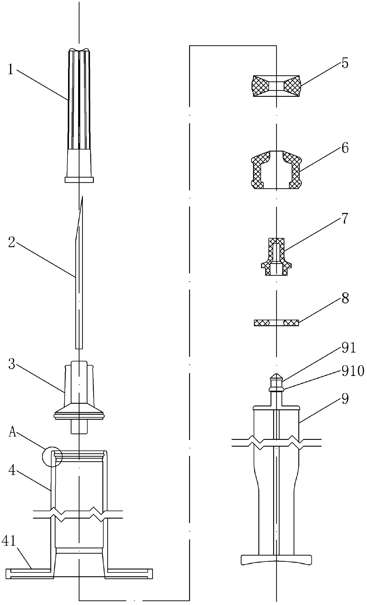
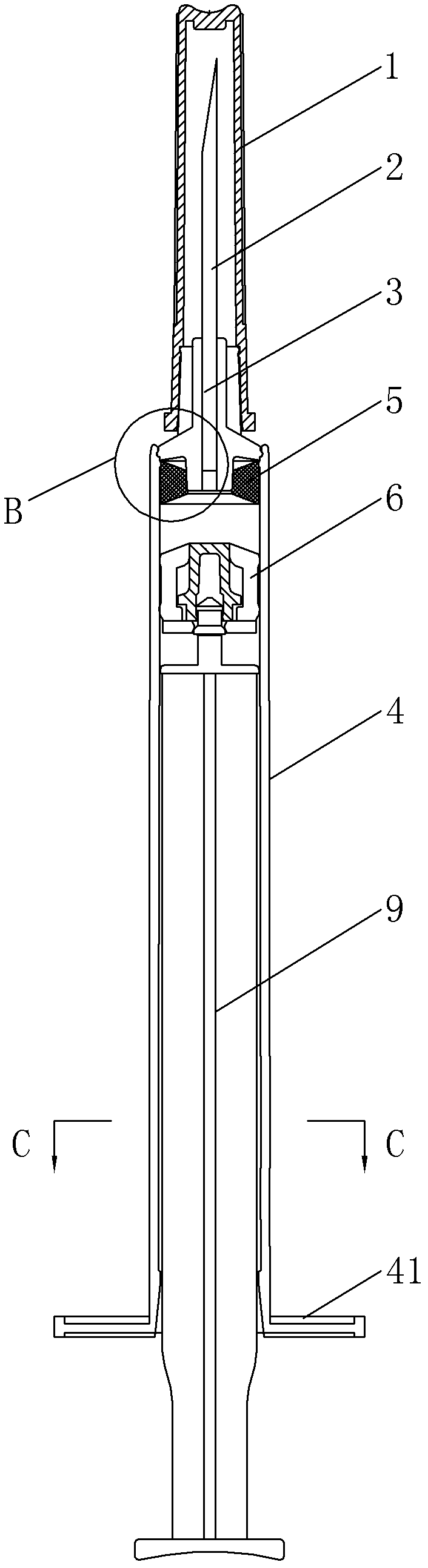
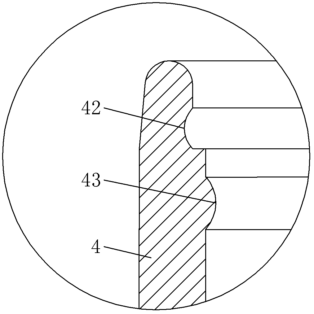
[0020] Example 1, such as Figure 1-6 As shown, a ejection self-destructing syringe includes a syringe 4, an injection rod 9, a needle seat 3 and a needle 2 fixed on the needle seat 3, and the needle seat 3 is provided with a channel connecting the needle 2 and the syringe 4. The liquid hole, the upper end of the injection rod 9 is provided with a piston 6, and the inner wall of the end of the injection cylinder 4 connected to the needle seat 3 is formed with an annular groove 42, and the lower end of the needle seat 3 is formed with the groove 42. The matching rib 31, the needle base 3 on the lower side of the rib 31 is covered with a sealing ring 5 that is in close contact with the inner wall of the injection barrel 4, and the sealing ring 5 ensures that the medicinal liquid will not pass through the needle base 3 and the injection barrel during injection 4's fitting clearance bleeds out to the outside.

[0021] The middle part of the upper end of the above-mentioned inject...

Embodiment 2

[0025] Example 2, such as Figure 7 with Figure 8 As shown, this embodiment is basically the same as Embodiment 1, the difference is that: the upper end of the syringe 4 is radially retracted to form a needle seat installation part 46, and a groove 42 is formed on the inner wall of the upper end of the needle seat installation part 46, The needle base 3 is formed with a convex rib 31 that snaps into the groove 42, and the lower part of the needle base 3 is provided with a sealing ring 5, and the limiting convex rings on the upper and lower sides of the sealing ring 5 (43 is the upper limit convex ring, 45 is the lower limit convex ring) are all molded on the inner wall of the needle holder mounting part 46 of the injection cylinder, the needle holder 3 of this embodiment can be pushed out of the injection cylinder 4 by the injection rod 9, while the sealing ring 5 cannot be pushed out ( The shape of the upper limit protruding ring 43 determines whether the sealing ring 5 can...


PUM


Abstract

The present invention relates to the technical field of disposable syringes. A pushout self-destructive syringe, comprising a syringe cartridge (4), a syringe rod (9), a needle seat (3), and a needle (2) fixed on the needle seat (3); the needle seat (3) is provided with a liquid flowing hole therein for the needle (2) to communicate with the syringe cartridge (4); a piston (6) is arranged at the upper end of the syringe rod (9); a rib (31) is formed at the lower part of the needle seat (3); a mounting portion is formed on the inner wall at the end of the syringe cartridge (4) connected with the needle seat (3); the mounting portion engages the rib (31) to prevent the needle seat (3) from slipping out of the syringe cartridge (4); the needle seat (3) below the rib (31) is sleeved with a seal ring (5) tightly pressing against the inner wall of the syringe cartridge (4); when the syringe rod (9) is pushed up to a predetermined position, the needle seat (3) can overcome the resistance applied to the rib (31) by the mounting portion, such that the needle seat (3) is pushed out of the syringe cartridge (4). After an injection is completed, the needle seat (3) can be easily pushed out of the syringe cartridge (4) by simply re-applying force to the syringe rod (9), so as to realize syringe self-destruction. The present invention has a reasonable structure, and a lower production cost, and is easy to recycle after product use, and is suitable for medical care personnel to use.

Description

technical field [0001] The invention belongs to the technical field of disposable syringes, in particular to a ejector self-destructing syringe. Background technique [0002] With the progress and development of society, people's requirements for medical treatment are getting higher and higher, and medical devices are also constantly innovating and improving, especially the improvement in syringes has been greatly improved. At present, disposable plastic syringes have been widely used. Ordinary disposable syringes are discarded after one use, which can prevent virus infection caused by the reuse of the syringes, which is safer and hygienic. However, the disposable syringes currently on the market are troublesome to use due to their complicated structural design, and they cannot be completely self-destructed, and their production costs are relatively high, which is not conducive to popularization. Contents of the invention [0003] The purpose of the present invention is ...

Claims


Application Information

Patent Timeline
Patent Type & Authority Patents(China)
IPC IPC(8): A61M5/178A61M5/50A61M5/31
CPCA61M5/50A61M5/32A61M5/3134A61M2005/3206A61M2005/5006
Inventor 蔡根顺
Owner 洪铭婉
Why Eureka
Try Eureka