Shape-Controllable Catheters and Catheter Systems

A technology for catheters and catheter parts, applied in catheters, guide wires, surgery, etc., can solve the problems of probe thickness and volume, user discomfort, and limited versatility of the probe system

Active Publication Date: 2016-08-03
SIEMENS MEDICAL SOLUTIONS USA INC
View PDF8 Cites 0 Cited by
  • Summary
  • Abstract
  • Description
  • Claims
  • Application Information

AI Technical Summary

Problems solved by technology

The thickness and bulk of these probes create user discomfort
Furthermore, the versatility of these probe systems is limited

Method used


Image

  • Shape-Controllable Catheters and Catheter Systems
  • Shape-Controllable Catheters and Catheter Systems
  • Shape-Controllable Catheters and Catheter Systems

Examples


Embodiment Construction

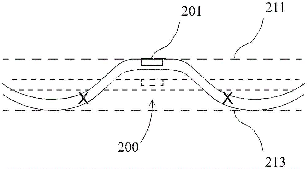
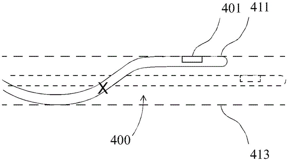
[0016] In the following detailed description, a catheter system is described and a shape-controllable catheter is described that can be manipulated to form a curved shape, either a simple curved shape or a compound curved shape. In the relaxed state, insertion of the catheter into the body is easily accomplished. In the non-relaxed state, contact conditions favorable for quality operation can be obtained. For example, in the case of imaging operations, close and uniform contact of the imaging array with the body wall can be achieved.

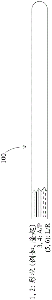
[0017] refer to Figure 1A and 1B , shows a perspective view of a portion of an exemplary catheter 100 that can be manipulated to form a compound curved shape, such as a concave bend. Catheter 100 may be described as a "bump-shaped" catheter because catheter 100 can be manipulated ( Figure 1B ) to form a bulge before the end of the catheter 100. In the case of an ultrasound catheter system, the ultrasound array 101 may be located at the pe...


PUM


Abstract

The present invention relates to shape controllable catheters and catheter systems. A shape-controllable catheter (100, 200, 300, 400, 500) is provided that is versatile in application and minimizes or reduces patient discomfort in human imaging applications. One such catheter is provided with: at least one control wire (121, 123) extending inside the catheter; and a control mechanism (611, 613) for tensioning the control wire to create a raised shape or cantilevered structure. The stiffness of the catheter can vary along its length to induce the desired bend. For example, the stiffness can be reduced in the bending region. Stiffness may be maintained or increased in other areas for performance reasons, eg, to maintain planarity of the imaging array.

Description

technical field [0001] The present invention relates to catheters and catheter systems including ultrasound catheter systems. Background technique [0002] Various catheter systems are known, including ultrasound catheter systems. One such catheter system is the assignee's AcuNav™ catheter system. Such as Figure 6 As shown in , in one application, the system uses an ultrasound array 601 mounted at the end of a small diameter catheter 603 to gain access to the heart through the venous system for ultrasound images. Steering of the tip of catheter 604 is performed using control wires (not shown), which pass through the lumen inside catheter 603 . Using four control lines, both front / back (A / P) and right / left (R / L) control can be achieved. The operator handle 610 is provided with two rotating rings 611 and 613, one for A / P control and one for R / L control. Found in U.S. Patents 5,938,616 and 5,846,205 Figure 6 Additional details of the system. [0003] Another known system...

Claims


Application Information

Patent Timeline
Patent Type & Authority Patents(China)
IPC IPC(8): A61B8/12
CPCA61B8/445A61M25/0082A61M25/0141A61M25/0147A61M2025/0161A61B8/12A61M25/01A61M25/09
Inventor L.J.加比尼M.拉希米
Owner SIEMENS MEDICAL SOLUTIONS USA INC
Why Eureka
Try Eureka