Elevator car frame
A car frame and elevator technology, which is applied in the field of car frames, can solve the problems of increased weight of the car frame, inability to easily cope with changes in the design of anti-vibration parts, and an increase in the number of components.
- Summary
- Abstract
- Description
- Claims
- Application Information
AI Technical Summary
Problems solved by technology
Method used
Image
Examples
Embodiment approach 1
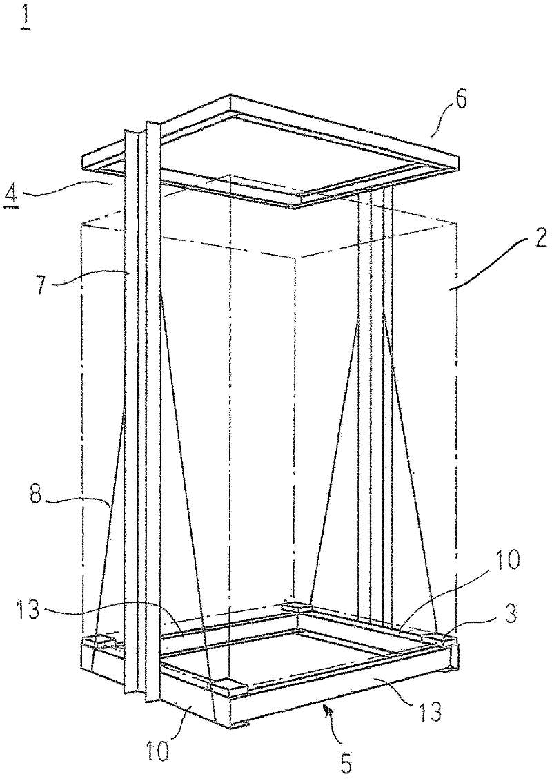
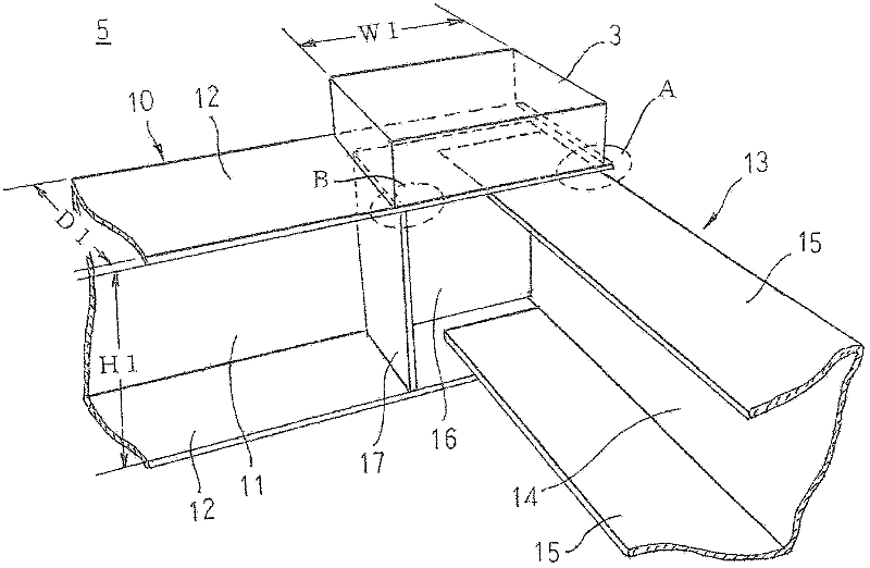
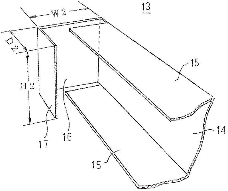
[0029] figure 1 is a perspective view schematically showing the structure of an elevator car according to Embodiment 1 of the present invention, figure 2 It is a perspective view of important parts for explaining the car room support structure in the car frame of the elevator according to Embodiment 1 of the present invention, image 3 It is a perspective view of important parts showing the structure of the beam in the car frame of the elevator according to Embodiment 1 of the present invention.
[0030] exist figure 1 Among them, the car 1 includes: a car room 2; and a car frame 4, which supports the car room 2. The car frame 4 includes: a bottom frame 5, which is arranged directly below the car bottom of the car room 2 through an anti-vibration rubber 3 as a vibration-proof member, and is used to support the load of the car room 2; an upper frame 6 , which is arranged on the upper part of the ceiling of the car room 2; vertical frames 7, which are arranged upright on bot...
Embodiment approach 2
[0048] Figure 4 It is a perspective view of important parts for explaining the car room support structure in the car frame of the elevator according to Embodiment 2 of the present invention, Figure 5 It is a perspective view of important parts showing the structure of the beam in the car frame of the elevator according to Embodiment 2 of the present invention.
[0049] exist Figure 4 and Figure 5 Among them, the first folded portion 16 is formed to have the same length as the width of the flange portion 15 . And the beam 13A is comprised by welding the 1st folded part 16, the 2nd folded part 17, and the two flange parts 15 together.
[0050] The two ends of a pair of cross beams 13A constituted in this way are inserted into the longitudinal end sides of the front and rear beams 10, and the pair of cross beams 13A are arranged so that the opening sides of the U-shaped cross section face each other. parallel. At this time, the distal end surfaces of the second folded-ba...
Embodiment approach 3
[0056] Figure 6 It is a perspective view of important parts for explaining the car room support structure in the car frame of the elevator according to Embodiment 3 of the present invention, Figure 7 It is a perspective view of important parts showing the structure of the beam in the car frame of the elevator according to Embodiment 3 of the present invention.
[0057] exist Figure 6 and Figure 7 Among them, the first folded portion 16 is formed by bending from both ends of the web portion 14 in the longitudinal direction relative to the web portion 14 at an angle greater than 90 degrees.
[0058] The two ends of a pair of beams 13B constituted in this way are inserted into the longitudinal end sides of the front and rear beams 10, and the pair of beams 13B are arranged so that the opening sides of the U-shaped cross section face each other. parallel. At this time, the tip of the first folded portion 16 is located near the intersection where the edge portion on the inn...
PUM
 Abstract
Description
Claims
Application Information
 - R&D
- Intellectual Property
- Life Sciences
- Materials
- Tech Scout
- Unparalleled Data Quality
- Higher Quality Content
- 60% Fewer Hallucinations
Browse by: Latest US Patents, China's latest patents, Technical Efficacy Thesaurus, Application Domain, Technology Topic, Popular Technical Reports.
© 2025 PatSnap. All rights reserved.Legal|Privacy policy|Modern Slavery Act Transparency Statement|Sitemap|About US| Contact US: help@patsnap.com


