Card reader

a card reader and card reader technology, applied in the field of card readers, can solve the problems of difficulty in re-designing the intensity, waterproofness, reading performance, reading distance and communication success ratio, against the reader housing, etc., and achieves the effect of reducing the size, such as the area or the number of turns, and facilitating the design chang

Active Publication Date: 2017-07-11
DENSO WAVE INC
View PDF14 Cites 0 Cited by
  • Summary
  • Abstract
  • Description
  • Claims
  • Application Information

AI Technical Summary

Benefits of technology

[0009]According to the card reader of this example, attaching of the switch unit to the housing and providing of the third antenna inside of the housing allow the reliable wireless communication between the switch unit and the control circuit by using the RF tag. Attaching the switch unit to the housing thus eliminates the needs of changes in the internal wiring or changes in the housing structure, such as boring a hole in the housing for wiring. This facilitates the design changes such as change of the attachment position of the switch unit and adding a new switch unit. In addition, according to the card reader of this example, the third antenna is used for communicating with the second antenna of the switch unit, allowing the second antenna to be arranged adjacent to the third antenna. This enables to reduce the size, such as an area or the number of turns, of the third antenna and facilitate the re-arrangement of the third antenna when needed in moving or adding a switch unit. Further, the third antenna having a compact size allows easy design change when the card reader is prepared by changing the design of a conventional card reader that connects a press-button switch unit to a control circuit with wiring.

Problems solved by technology

The design changes typically include changes of housing or internal wiring for installing switch units, unfortunately leading to difficulties in re-designing the intensity, waterproofness, and reading performance including reading distance and communication success ratio, against the housing of the reader.

Method used


Image

  • Card reader
  • Card reader
  • Card reader

Examples


first embodiment

A. First Embodiment

A-1. Configuration

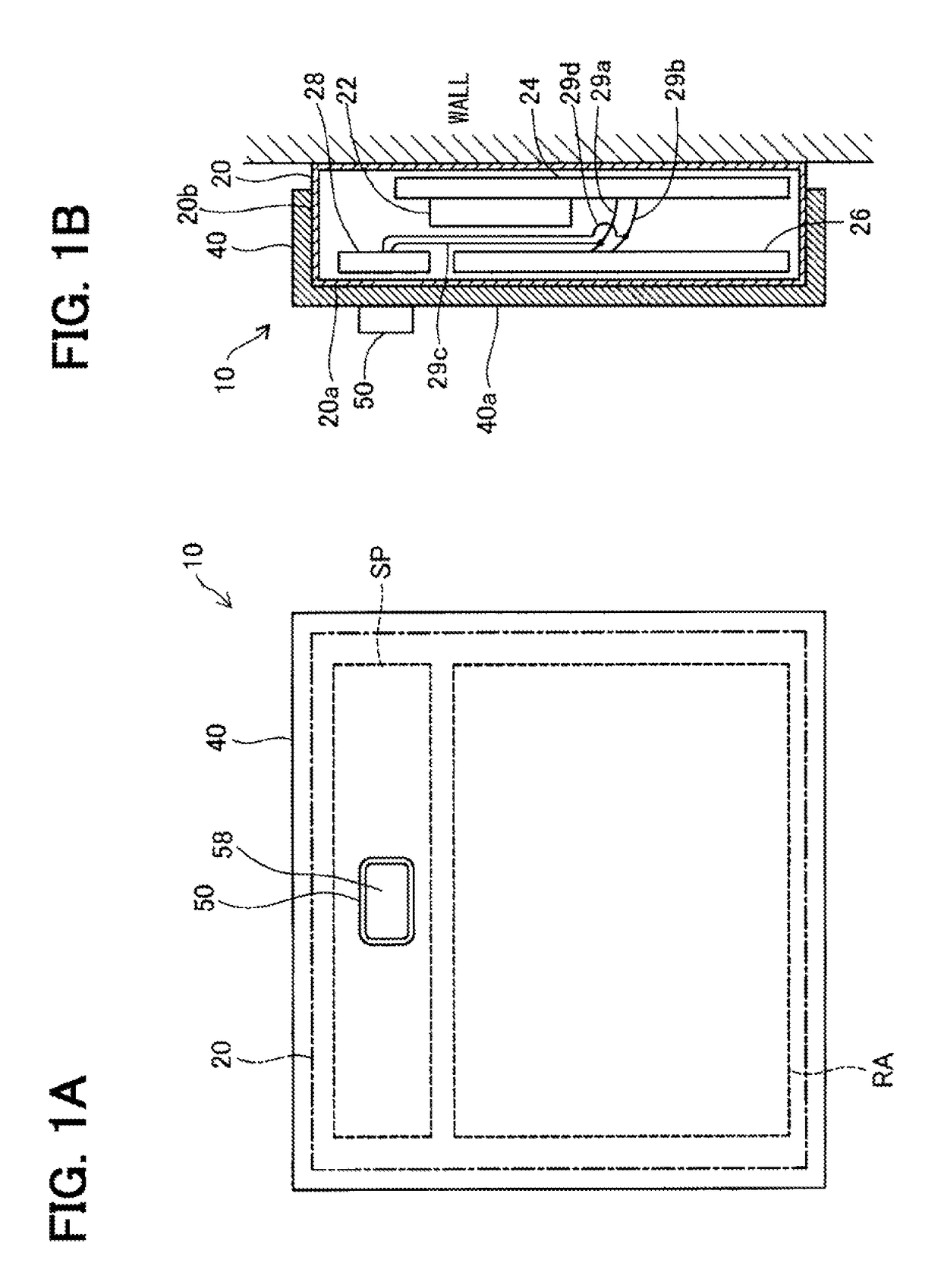
[0022]A card reader 10 according to a first embodiment of the present disclosure is illustrated in FIGS. 1A and 1B. FIG. 1A illustrates a front view; FIG. 1B illustrates a partial cross-sectional side view. The card reader 10 is an apparatus for reading information in an identification (ID) card that is unshown. The present embodiment provides the card reader 10 that is included in an access control system managing access controls for entering and exiting offices, for instance. The ID card is a contactless integrated circuit (IC) card, which may be also referred to a non-contact IC card, for personal identification or personal authentication; the ID card is required to be held by office employees in offices, for instance.

[0023]As in FIGS. 1A and 1B, the card reader 10 includes a main body 20, a cover 40, and a press-button switch unit 50.

[0024]The main body 20 is shaped of a box having a front plate part 20a, a side plate part 20b, and a back pla...

second embodiment

B. Second Embodiment

[0060]A card reader 210 according to a second embodiment of the present disclosure is illustrated in FIGS. 7A and 7B. FIG. 1A illustrates a front view; FIG. 1B illustrates a partial cross-sectional side view. The card reader 210 of the second embodiment is different from the card reader 10 of the first embodiment in the attachment position of the press-button switch unit and the arrangement position of the auxiliary loop antenna. Other components of the card reader 210 of the second embodiment, which are identical to those of the card reader 10 in the first embodiment, are assigned with the same reference numerals as those in FIGS. 1A and 1B without further explanation.

[0061]The auxiliary loop antenna 228 faces the side plate part 20b on the upper side of the main body 20, as illustrated. That is, the loop plane of the auxiliary loop antenna 228, which is parallel with a horizontal plane, faces the side plate part 20b on the upper side of the main body 20. The pr...

third embodiment

C. Third Embodiment

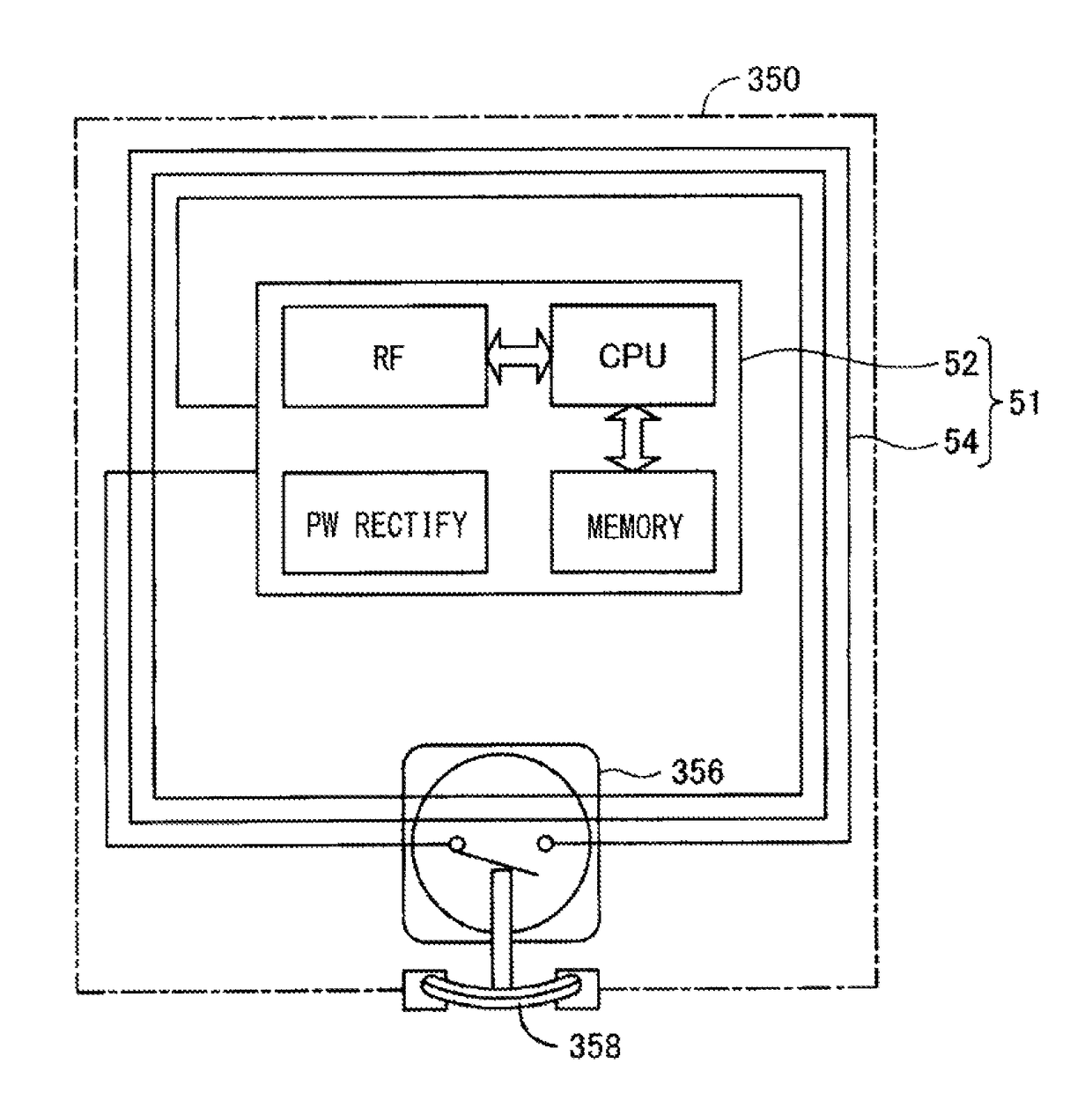
[0065]FIG. 8 is a diagram for explaining an internal configuration of a temperature switch unit 350 included in a card reader according to a third embodiment of the present disclosure. The temperature switch unit 350 in the third embodiment has a configuration corresponding to that of the press-button switch unit 50 in the first embodiment; the card reader of the third embodiment includes a main body and a cover identical to those of the first embodiment, in addition to the temperature switch unit 350.

[0066]The temperature switch unit 350 is different from the press-button switch unit 50 of the first embodiment in that the manipulation portion 58 (see FIG. M) is replaced with a bimetal 358, as in FIG. 8. The bimetal 358, which is arranged to be exposed from the front face of the temperature switch unit 350, functions as a temperature detection part. The attachment position of the temperature switch unit 350 to the cover is the same as that of the press-button swit...


PUM


Abstract

A card reader to read information in an integrated circuit (IC) card includes a housing, a first antenna, a control circuit, a switch unit, and a third antenna. The first antenna is disposed inside of the housing. The control circuit is to communicate with the IC card within a communication range of the first antenna and perform at least a process that acquires data from a memory in the IC card. The switch unit is provided to the housing and includes a radio frequency (RF) tag that includes a second antenna. The third antenna is disposed inside of the housing. The switch unit functions as a switch that performs a predetermined function by causing the RF tag to communicate with the control circuit via the second antenna and the third antenna when a predetermined condition is satisfied.

Description

CROSS REFERENCE TO RELATED APPLICATION[0001]The present application is based on Japanese Patent Application No. 2014-162692 filed on Aug. 8, 2014, the disclosure of which is incorporated herein by reference.TECHNICAL FIELD[0002]The present disclosure relates to a card reader that reads the information in an integrated circuit (IC) card.BACKGROUND ART[0003]Patent Literature 1: JP 2003-006578 A[0004]Access control systems are conventionally known to use contactless IC cards for access controls of entering and exiting facilitates, such as offices, warehouses, hospitals (for example, see Patent Literature 1). Such access control systems require each user to only bring his / her contactless IC card in proximity of the card reader installed adjacent to a door of a room to activate wireless communication to immediately identify the user, thereby unlocking the electric lock to permit the user to enter the room.[0005]Some access control systems are further known to install a press-button switc...

Claims


Application Information

Patent Timeline
Patent Type & Authority Patents(United States)
IPC IPC(8): G06K7/10
CPCG06K7/10356
Inventor HIRAIWA, YOSUKE
Owner DENSO WAVE INC
Why Eureka
Try Eureka