Eureka AIR delivers breakthrough ideas for toughest innovation challenges, trusted by R&D personnel around the world.

Antenna arrangement for ceiling mounted device

a technology for ceiling mounted devices and antennas, which is applied in fixed installation, lighting and heating equipment, and support devices for lighting, etc., can solve the problems of intrinsically difficult to fit electrically small antennas to a conductive body, flanges may be exposed to possible damage,

Pending Publication Date: 2022-08-18
ZUMA ARRAY LTD
View PDF0 Cites 0 Cited by
  • Summary
  • Abstract
  • Description
  • Claims
  • Application Information

AI Technical Summary

Benefits of technology

The invention aims to offer affordable antennas that can support reliable wireless communication for a device mounted in the ceiling.

Problems solved by technology

The flange may be exposed to possible damage during the installation of the device.
Fitting electrically small antennas to a conductive body is intrinsically difficult.

Method used


Image

  • Antenna arrangement for ceiling mounted device
  • Antenna arrangement for ceiling mounted device
  • Antenna arrangement for ceiling mounted device

Examples


experimental narrative

[0129]A number of sample antennas were provided on 0.8-mm thick 370HR produced by a milling machine.

[0130]FIG. 12 illustrates the sample P1. FIG. 13 illustrates the impedance of P1

[0131]Sample 1 was fitted with via rivets and after adjustment produced the impedance shown in FIG. 13. The frequency of the two working bands is approximately correct. The impedance plot has a loop passing close to the chart centre at 2.4 GHz and curled round the centre at 5 GHz. This is the expected behaviour, but the impedance needs improving by getting a tighter curl at 5 GHz without degrading 2.4 GHz.

[0132]The impedance was measured with the antenna grounded to the chassis, separated by a thick card and also mounted using double sided tape. the results are slightly different in each case, but by much less than with the original version. The feed cable was wrapped three times through a ferrite ring to decouple the cable, but the effect of the cable is now much less than with the original breadboard mod...


PUM

PropertyMeasurementUnit
wavelengthsaaaaaaaaaa
lengthaaaaaaaaaa
widthaaaaaaaaaa

Abstract

An antenna is provided. The antenna comprises a dielectric lamina having a first face and a second face opposite the first face. The antenna further comprises a groundplane on the first face of the dielectric lamina, wherein the groundplane is a planar conductive groundplane comprising first and second L-shaped apertures. The antenna further comprises a microstrip transmission line on the second face of the dielectric lamina.

Description

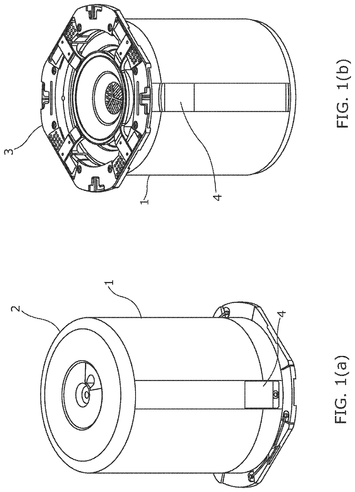
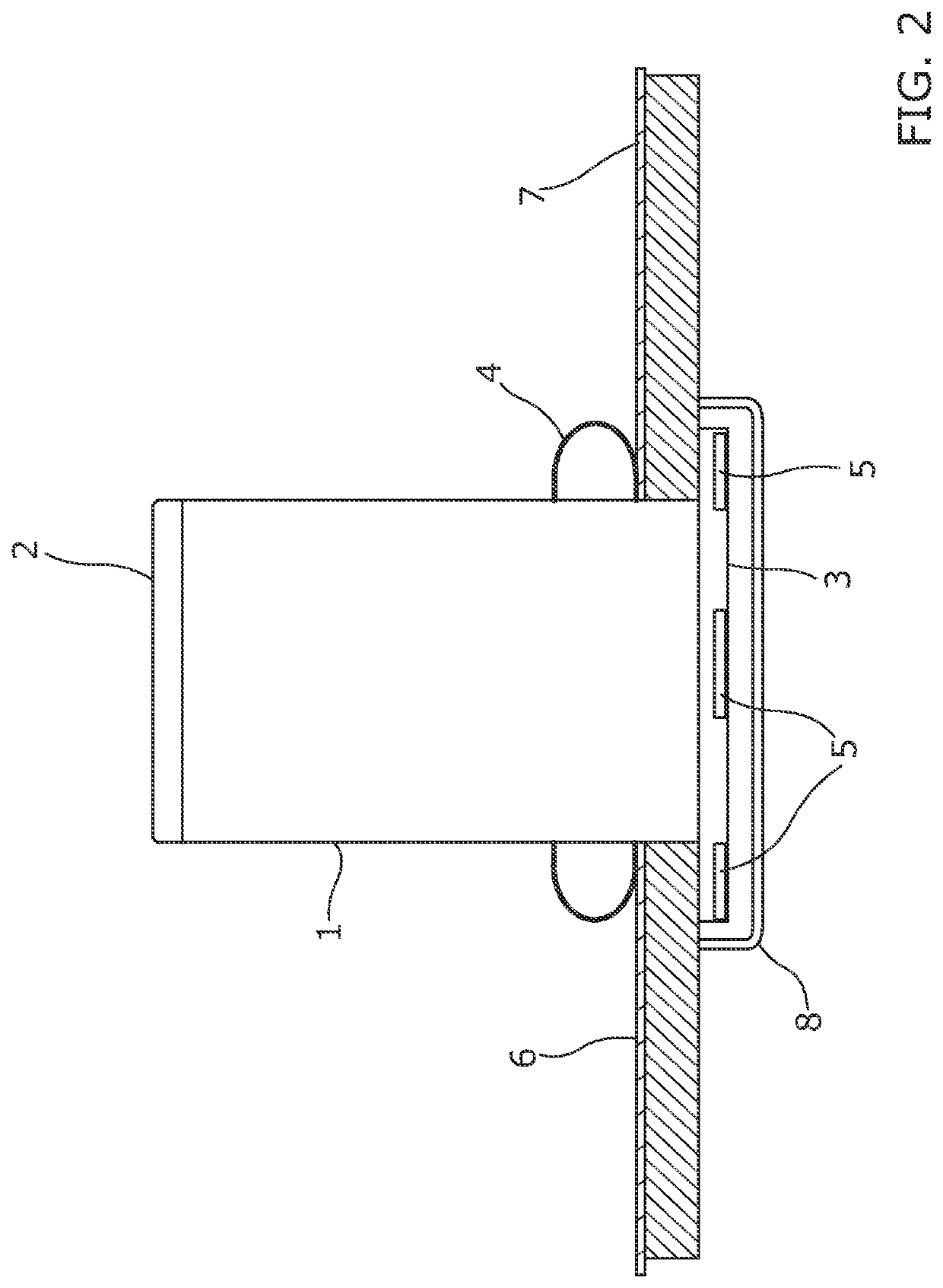
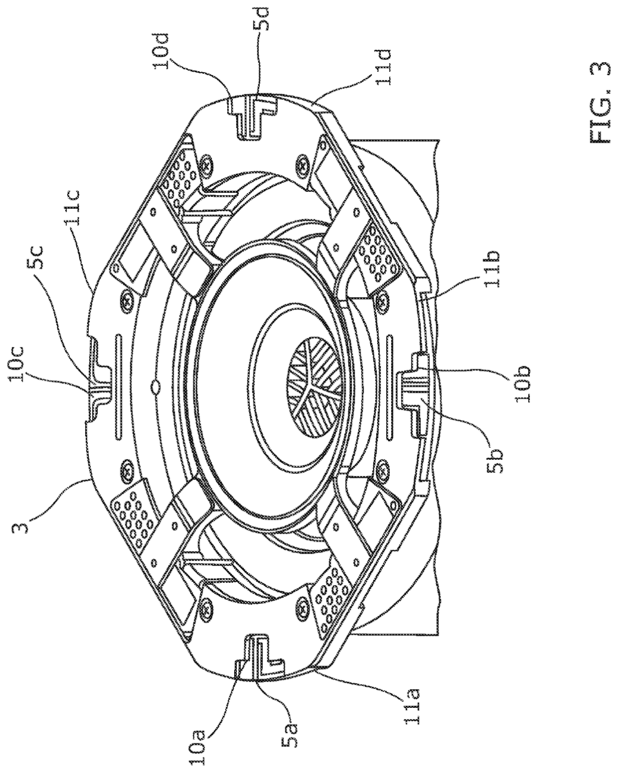
OBJECT OF THE INVENTION[0001]The object of the invention is to provide low cost antennas supporting reliable wireless communications for a ceiling mounted device.BACKGROUND OF THE INVENTION[0002]A ceiling-mountable loudspeaker and lighting system is housed in a cylindrical electrically conductive housing having a closed upper end and an open lower end, the lower end having an outwardly projecting flange whose primary function is to locate the housing against the lower surface of a ceiling or other supporting structure. The supporting ceiling may typically be constructed from plasterboard, medium density fiberboard (MDF) or plywood. The space inside the cylindrical housing is filled with functional components such as loudspeaker drivers and LED lights, and further electronics circuits may be connected to the circuits and devices within the housing by means of external cables.[0003]It is required to provide wireless communications with the contained and connected electronics circuits,...

Claims


Application Information

Patent Timeline
Patent Type & Authority Applications(United States)
IPC IPC(8): H01Q1/00H01Q1/44H01Q9/04H01Q1/48H01Q5/357H04R1/02F21S8/02F21V33/00F21V21/04
CPCH01Q1/007H01Q1/44H01Q9/0421H01Q1/48H01Q5/357H04R2201/021H04R1/026F21S8/026F21V33/0056F21V21/044H04R1/028H01Q1/22H01Q5/10H01Q5/20H01Q5/35H01Q21/28H01Q5/40H01Q13/10H01Q13/16H01Q5/364
Inventor WARREN, MORTENROSE, EDWARDCOLLINS, BRIAN
Owner ZUMA ARRAY LTD
Why Eureka
Eureka Blog
Learn More