
Fuel injection valve

A fuel injection valve, fuel injection technology, applied in the direction of fuel injection device, charging system, engine components, etc., to achieve the effect of easy design change

Active Publication Date: 2017-08-29
HITACHI ASTEMO LTD
View PDF5 Cites 0 Cited by
  • Summary
  • Abstract
  • Description
  • Claims
  • Application Information

AI Technical Summary

Problems solved by technology

Therefore, it takes a considerable amount of time to determine the diameter of the fuel injection hole, the length of the fuel injection hole, and the size (diameter) of the swirl chamber so that both the fuel injection amount and the spray angle are within a predetermined range.

Method used


Image

  • Fuel injection valve
  • Fuel injection valve
  • Fuel injection valve

Examples


Embodiment Construction

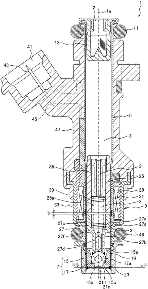
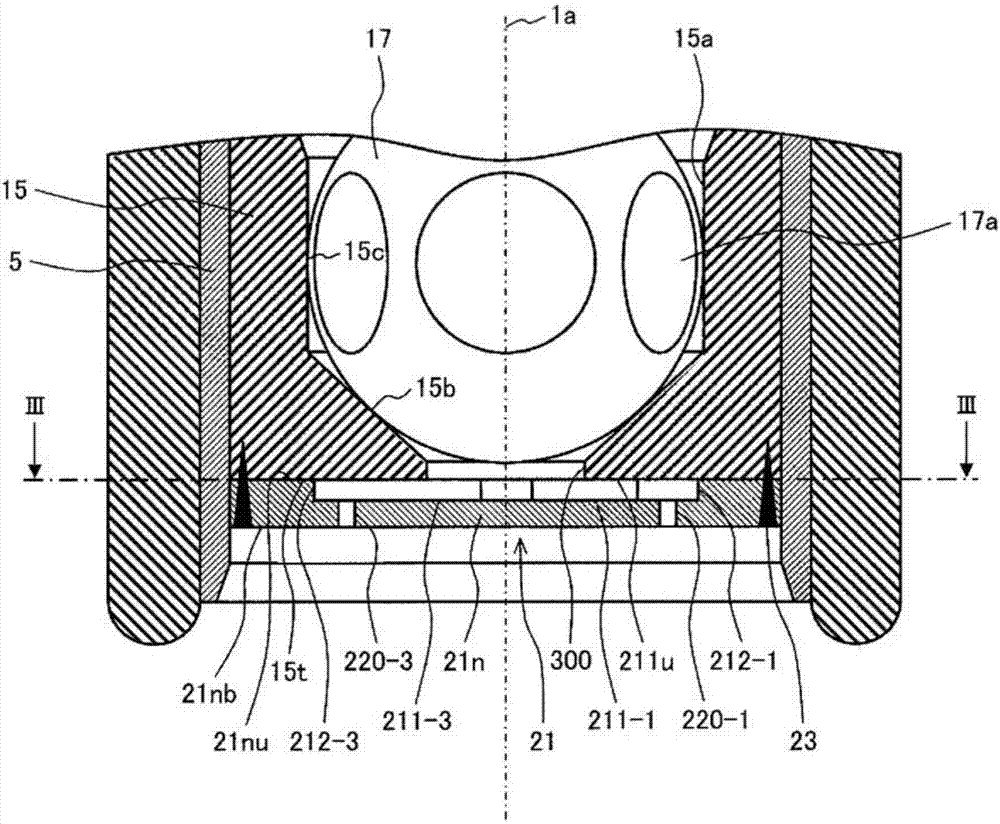
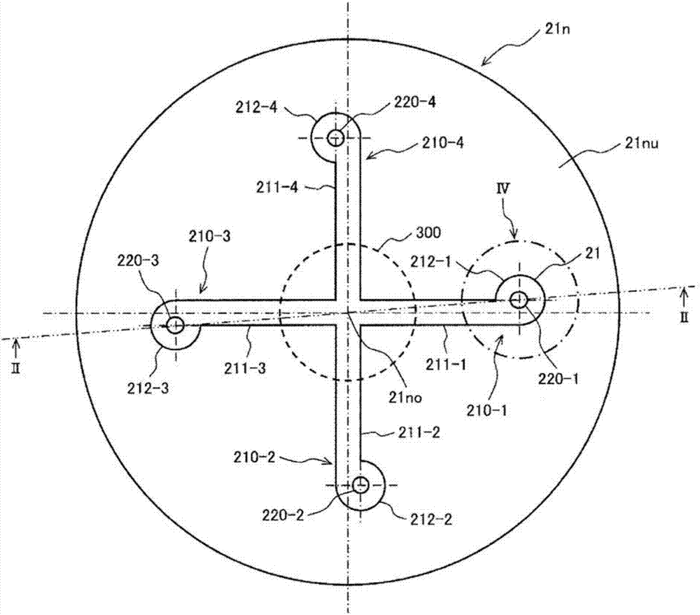
[0031] In the present embodiment, the valve portion 7 including the valve seat member 15 and the valve body 17 and the nozzle plate 21 n constitute a nozzle portion for injecting fuel. A nozzle plate 21n forming a fuel injection hole 220 and a swivel passage 210 (lateral passage 211 and swivel chamber 212 ) to be described later is joined to the front end surface of the nozzle body (valve seat member 15 ) constituting the valve portion 7 .

[0032] A drive unit 9 for driving the valve body 17 is disposed in the middle of the cylindrical body 5 . The driving unit 9 is constituted by an electromagnetic actuator. Specifically, the driving unit 9 is constituted by a fixed iron core 25 , a movable element (movable member) 27 , an electromagnetic coil 29 , and a yoke 33 .

[0033] The fixed core 25 is made of a magnetic metal material, and is press-fitted and fixed to the inner side of the middle portion in the longitudinal direction of the cylindrical body 5 . The fixed core 25 i...


PUM


Abstract

This fuel injection valve comprises: a fuel injection hole 220 provided on a downstream side of a valve seat which a valve body comes into contact with and separates from; a swirl chamber 212 in which a fuel swirl flow path 212d is formed around an inlet opening 220i of the fuel injection hole 220; and a lateral passage 211 which opens in an inner circumferential wall 212c and supplies fuel to the swirl chamber 212. A center O2 of the inlet opening 220i of the fuel injection hole 220 is disposed displaced from a first position O1 in which the swirl-direction velocity component of the fuel flowing into the fuel injection hole 220 is maximal, to a second position O2 in which the swirl-direction velocity component is reduced, and a velocity component in the central axial direction of the fuel injection hole 220 is increased. By this means it is possible for the fuel injection quantity and the spray angle to be easily adjusted.

Description

technical field [0001] The present invention relates to a fuel injection valve that generates swirling fuel upstream of a fuel injection hole and injects the swirling fuel from the fuel injection hole. Background technique [0002] A fuel injection valve described in JP-A-2003-336562 (Patent Document 1) is known as background art in this technical field. The fuel injection valve is formed with: a transverse passage communicating with the downstream end of the valve seat between the valve seat member and the injection plate joined to the front end surface of the valve seat member; Swirl chamber; in the fuel injection valve, the fuel injection hole for fuel injection after the swirl is applied to the swirl chamber is drilled in the injection plate, and the fuel injection hole is deviated from the center of the swirl chamber to the upstream end side of the transverse passage by a predetermined distance ( see abstract). In this fuel injection valve, atomization of the injected...

Claims


Application Information

Patent Timeline
IPC IPC(8): F02M51/06F02M51/08F02M61/18
CPCF02M51/06F02M61/18F02M61/1853F02M51/061F02M61/162F02M61/1806F02M63/0031
Inventor 长冈正树小林信章木下隆太
Owner HITACHI ASTEMO LTD
Learn More