Light source system, illuminating device and projecting device

A technology of a light source system and a light source device, which is applied in the field of optics, can solve problems such as increasing the cost of the light source system, unfavorable miniaturization of the light source system, and larger volume of the light source system, and achieves the effects of reducing volume, quantity, and cost

Active Publication Date: 2012-08-22
APPOTRONICS CORP LTD
View PDF7 Cites 49 Cited by
  • Summary
  • Abstract
  • Description
  • Claims
  • Application Information

AI Technical Summary

Problems solved by technology

However, in the above solution, three color wheels 202A, 202B and 202C are needed, which increases the volume of the light source system, which is not conducive to the miniaturization of the light source system and increases the cost of the light source system

Method used


Image

  • Light source system, illuminating device and projecting device
  • Light source system, illuminating device and projecting device
  • Light source system, illuminating device and projecting device

Examples


Embodiment Construction

[0040] The present invention will be described in detail below in conjunction with the accompanying drawings and embodiments.

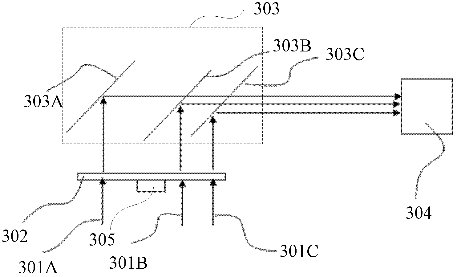
[0041] Such as image 3 As shown, the first embodiment of the light source system of the present invention includes three light sources (not shown), a color wheel 302 , an optical path combining system 303 , a light collecting device 304 and a driving device 305 .

[0042] The three light sources correspondingly generate three beams of incident light 301A, 301B and 301C. The color wheel 302 receives the three beams of incident light 301A, 301B and 301C at different positions, and correspondingly outputs three beams of outgoing light (not shown). The optical path combining system 303 performs optical path combining on the three beams of outgoing light, and the light collecting device 304 collects the three beams of outgoing light beams combined by the optical path combining system 303 for subsequent projection display or other applications.

[0043] ...


PUM


Abstract

The invention discloses a light source system, an illuminating device and a projecting device. The light source system comprises a color wheel and a light path combining system. The color wheel is used for receiving at least two bundles of incident lights at different positions and correspondingly outputting at least two bundles of emergent lights. The light path combining system is used for carrying out light path combination on at least two bundles of the emergent lights. The color wheel is provided with a first region; the first region receives first incident lights; and wavelength conversion is carried out on the first incident lights so as to generate first emergent lights. With the adoption of the manner, the quantity of the color wheel can be sufficiently reduced and the volume of the light source system is effectively reduced; and meanwhile, the cost of the light source system is effectively reduced.

Description

technical field [0001] The invention relates to the field of optics, in particular to a light source system, an illuminating device and a projection device. Background technique [0002] Multi-color light sources are widely used in various applications such as projection display and stage lighting. Such as figure 1 As shown, in a prior art light source system, the excitation light generated by the excitation light source 102 is condensed by the lens 103 and then incident on the color wheel 104 . The color wheel 104 is respectively provided with a plurality of phosphor regions along the circumferential direction, such as a green phosphor region, a red phosphor region and a blue phosphor region. The fluorescent color wheel 104 rotates under the drive of the driving device 105, so that the above-mentioned areas on the color wheel 104 are alternately arranged on the transmission path of the excitation light generated by the excitation light source 102, and then the excitation ...

Claims


Application Information

Patent Timeline
Patent Type & Authority Applications(China)
IPC IPC(8): G03B21/20G03B21/14G02B7/00G02B27/10F21S8/00F21V13/08G03B21/00
CPCG02B27/141H04N9/3114G03B21/2033G03B21/204G03B33/08
Inventor 胡飞
Owner APPOTRONICS CORP LTD
Why Eureka
Try Eureka