
Pneumatic tire

A technology for pneumatic tires and tires, applied in tire parts, tire tread/tread pattern, tire sidewall, etc., can solve the problems of increased tire mass and rubber volume, and achieve increased rubber volume and improved cutting resistance. performance, the effect of improving rigidity

Active Publication Date: 2012-08-29
SUMITOMO RUBBER IND LTD
View PDF6 Cites 18 Cited by
  • Summary
  • Abstract
  • Description
  • Claims
  • Application Information

AI Technical Summary

Problems solved by technology

[0005] However, since such raised portions c are continuously provided along the tire circumferential direction, there is a problem that the rubber volume increases and the tire mass increases.

Method used


Image

  • Pneumatic tire
  • Pneumatic tire
  • Pneumatic tire

Examples


Embodiment

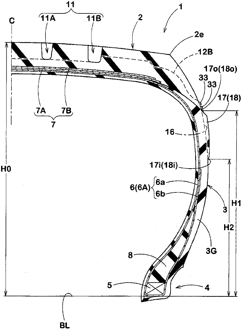
[0087] Manufacturing composition figure 1 The tires having the basic structure shown in Table 1 and the bumps shown in Table 1 were evaluated for their performance. Among them, the common specifications are as follows.

[0088] Tire size: LT315 / 75R16

[0089] Rim size: 16×8.0J

[0090] Tire section height H0: 235.85mm

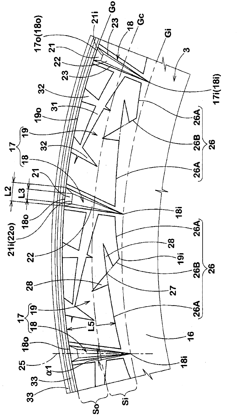
[0091] Width L2 in the tire circumferential direction of the outer wall surface: 4.8 to 6.4 mm

[0092] Width L3 in the tire circumferential direction of the inner wall surface: 2.9 to 3.9 mm

[0093] Circumferential side groove:

[0094] Angle α2: 8 to 14 degrees

[0095] Maximum width W2m: 3.5mm

[0096] radial side groove

[0097] Angle α3: 12 to 32 degrees

[0098] Maximum width W3m: 3.0 to 5.0 degrees

[0099] Circumferential rib:

[0100] Bump height L6(mm): 1.5mm

[0101] Interval W4 (mm): 3mm


PUM


Abstract

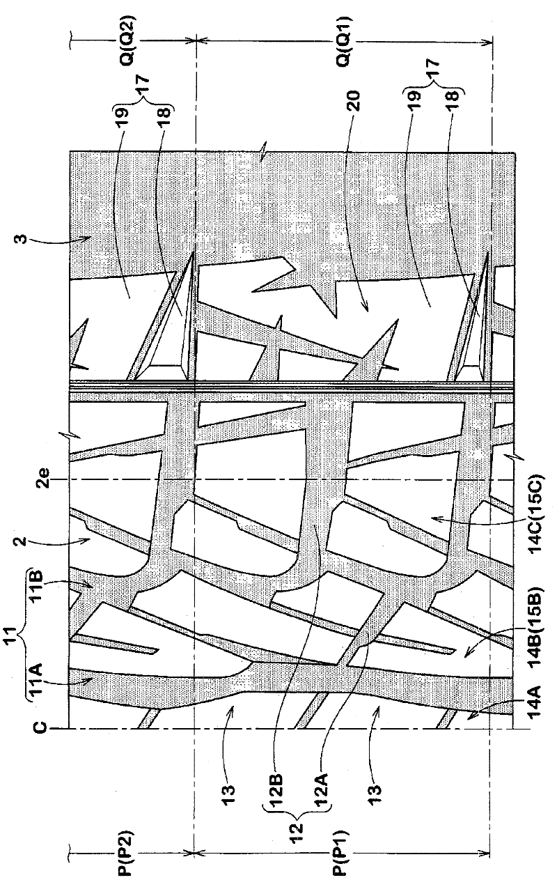
The invention provides a pneumatic tire which can maintain high cutting resistance and operation stability and restrain increase of tire weights. The pneumatic tire (1) includes a tread portion (2), sidewall portions (3) and bead portions (4).A protrusion (17) protruding on a tire side reference outside surface (16) is formed on at least one of the sidewall portions (3). The protrusion (17) includes a plurality of longitudinal ribs (18) and a low height part (19). Each rib has a protruding height of 0.5 to 7.0 mm from the normal outer surface of the sidewall. Each low height part has a protruding height from the normal outer surface of the sidewall that is lower than that of the longitudinal ribs. The sidewall portion with the protrusion has a ratio between a total area (A1) of the protrusion projected onto the normal outer surface of the sidewall portion and an area between an outer circumferential line (Go) on the sidewall portion passing through a radially outmost point (17o) of the protrusion (17) and an inner circumferential line (Gi) on the sidewall portion passing through a radially innermost point (17i) of the protrusion in a range of from 50 to 80%.

Description

technical field [0001] The present invention relates to a pneumatic tire capable of maintaining cut resistance and handling stability and suppressing an increase in tire mass. Background technique [0002] Pneumatic tires used for vehicles such as four-wheel-drive vehicles and trucks that run on poor roads may collide with sharp stones or the like on the sidewalls of the tires and cause cuts on the sidewalls. In addition, there is a problem that the sidewall portion is likely to be twisted due to a large load acting on the pneumatic tire, and the steering stability is likely to be lowered. [0003] In the past, in order to deal with this problem, such as Figure 8 As shown in FIG. 2 , a raised portion c raised outward in the tire axial direction is provided on the outer surface of the sidewall portion a (see, for example, Patent Document 1 below). Such a raised portion c can improve the cut resistance, and increase the rigidity of the sidewall portion to improve steering st...

Claims


Application Information

Patent Timeline
Patent Type & Authority Applications(China)
IPC IPC(8): B60C13/02
CPCB60C11/11B60C13/02B60C11/03B60C17/08B60C11/01B60C11/0318
Inventor 松田阳介
Owner SUMITOMO RUBBER IND LTD
Learn More