Point pouring gate injection mould capable of automatically pushing out condensed materials

A point gate, injection mold technology, applied in the field of point gate injection mold, can solve the problems affecting the stability and reliability of the mechanism, high requirements for inclined holes, etc., to achieve the effect of compact mold, perfect function, and avoid damage

Inactive Publication Date: 2012-09-05
中山市兆格尔模具有限公司
View PDF5 Cites 8 Cited by
  • Summary
  • Abstract
  • Description
  • Claims
  • Application Information

AI Technical Summary

Problems solved by technology

The above-mentioned utility model utilizes the oblique hole (i.e. undercut) at the end of the runner to break the point gate, and the pulling rod pulls out the pouring system condensate and demoulds the point gate condensate, which has the following deficiencies: 1 , The requirements for the design of inclined holes are very high. The above structure must not only ensure that the pulling force on the condensate can pull the condensate of the gating system out of the cavity plate, but also allow the condensate of the gating system to be separated from the cavity plate as the parting surface is opened. The inclined hole is left on the movable mold part, so whether the inclined hole is reasonable or not will directly affect the stability and reliability of the mechanism
3. Since the pouring system aggregate must be separated from the inclined hole, the molded plastic is required to have a certain degree of toughness; and because the pouring system aggregate must undergo a certain deformation during demoulding, this form is only suitable for certain elasticity at the molding temperature. types of plastic

Method used


Image

  • Point pouring gate injection mould capable of automatically pushing out condensed materials
  • Point pouring gate injection mould capable of automatically pushing out condensed materials
  • Point pouring gate injection mould capable of automatically pushing out condensed materials

Examples


Embodiment 1

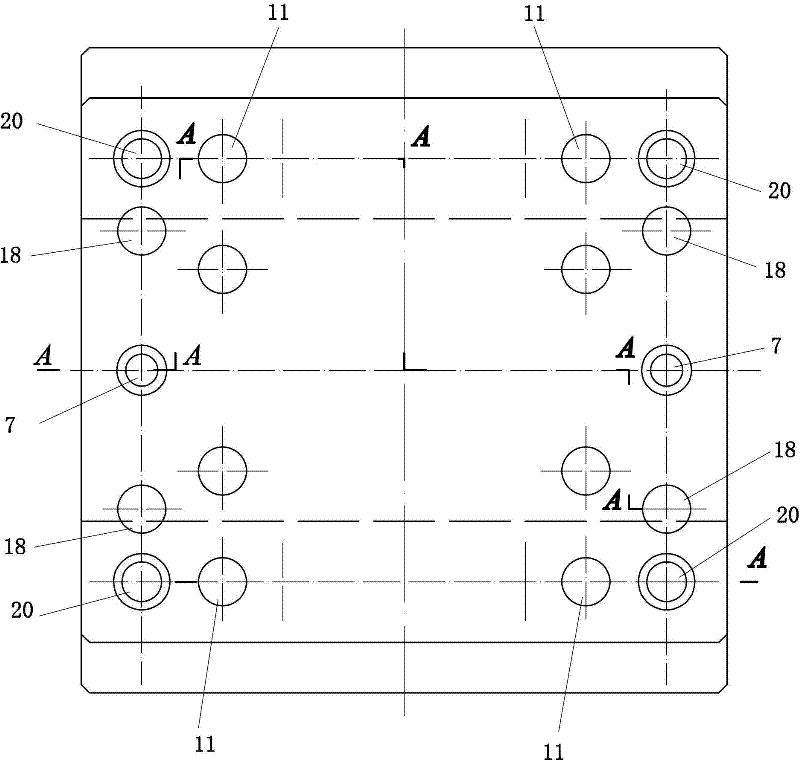
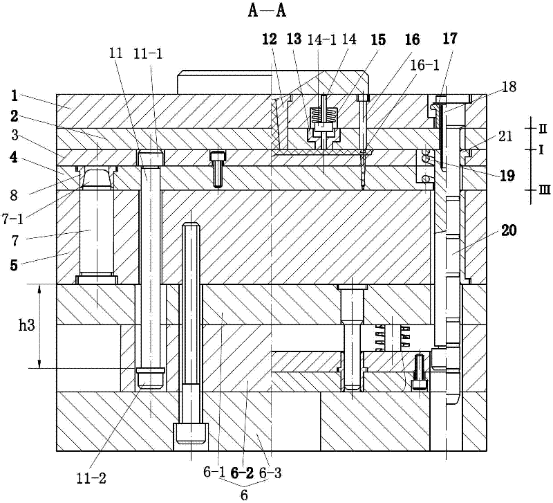
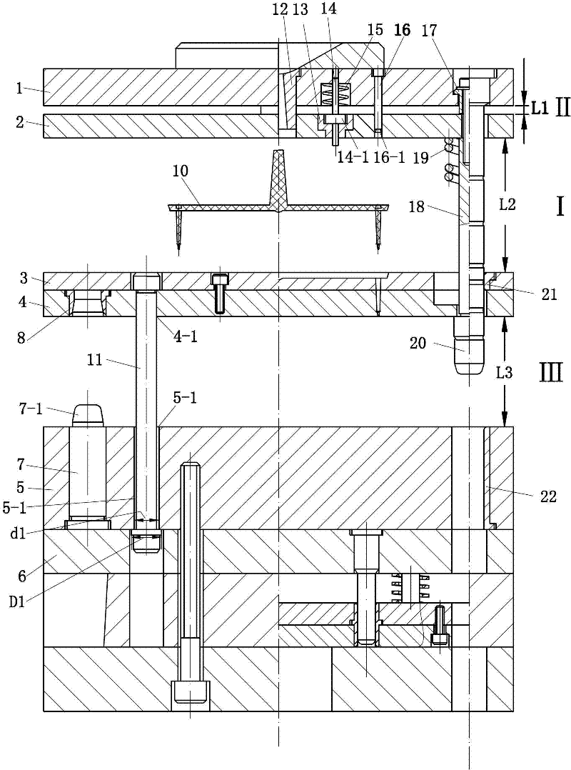
[0023] See attached Figures 1 to 7 , this embodiment includes a fixed mold seat plate 1, a de-gate plate 2, a runner plate 3, a fixed template 4, a movable template 5, and a movable mold seat 6 arranged in sequence from front to back, wherein the runner plate 3 and the fixed template 4 Connected together, movable template 4 and movable mold base 6 are connected together. Above-mentioned movable mold seat 6 is made up of movable mold backing plate 6-1, spacer 6-2 and movable mold base plate 6-3.

[0024] Between the fixed template 4 and the movable mold base 6, there are four first distance tie rods 11 connected by a hole shaft structure, and the first distance tie rods 11 are used to control the maximum parting distance between the fixed template 4 and the movable template 5 . Between the fixed mold base plate 1 and the movable mold base 6, there are four second distance tie rods 18 connected by a hole shaft structure, and the second distance distance tie rods 18 are used t...


PUM


Abstract

The invention provides a point pouring gate injection mould capable of automatically pushing out condensed materials. The point pouring gate injection mould comprises a fixed mould seat plate, a pouring gate removing plate, a split-flow channel plate, a fixed mould plate, a movable mould plate and a movable mould seat, wherein a first fixed-distance pull rod which is connected by using a hole shaft structure is arranged between the fixed mould plate and the movable mould seat; a second fixed-distance pull rod which is connected by using the hole shaft structure is arranged between the fixed mould seat plate and the movable mould seat; one part of the second fixed-distance pull rod, which corresponds to the fixed mould seat plate and the pouring gate removing plate, is fixedly provided with a fixed-distance sleeve; a separation compression spring for expanding the pouring gate removing plate and the split-flow channel plate is fixed on the second fixed-distance pull rod; pull rod through holes which are communicated with each other are arranged in the fixed mould seat plate and the pouring gate removing plate corresponding to each point pouring gate; each pull rod through hole is internally provided with a material pull rod and a reversed-tapered end of each material pull rod stretches into a split-flow channel in the split-flow channel plate; and a guide column which is connected by using the hole shaft structure is arranged between the fixed mould seat plate and the movable mould seat. The mould can be mounted on a horizontal injection machine, has the advantages of complete structure functions and reliable movement, prevents the appearance of a molded piece from being damaged to greatest extent, and can easily realize automatic and efficient injection production.

Description

technical field [0001] The invention relates to a point-gate injection mold for automatically pushing out condensate. Background technique [0002] Chinese Patent No. 200520033737. X’s utility model patent specification discloses an injection mold that automatically releases the pinpoint gate condensate, including a fixed mold plate, a fixed mold cavity plate and a movable mold plate. The fixed mold plate and the fixed mold cavity plate are guided and limited by tie rods and guide posts. , a compression spring is set on the pull rod; the fixed model cavity plate and the movable template are guided by the guide column, and the movable template is provided with a pull rod with a spherical head at the end; the pull rod passes through the fixed model cavity plate and has a cold The through hole of the material well; the end of the fixed formwork runner is provided with an oblique hole. When the fixed mold is just parting, the condensate in the gating system is hindered by the ...

Claims


Application Information

Patent Timeline
Patent Type & Authority Applications(China)
IPC IPC(8): B29C45/26B29C45/80B29C45/40
Inventor 江昌勇姜伯军
Owner 中山市兆格尔模具有限公司
Why Eureka
Try Eureka