Supercharge Your Innovation With Domain-Expert AI Agents!

Lift type pickup roller mechanism

A pick-up roller and lift-type technology, which is applied in the design and manufacture of printer equipment, can solve problems such as scratches and affect printing quality, achieve good results, improve printing quality, and have a reasonable and compact structure

Active Publication Date: 2014-06-04
KONG YUE ELECTRONICS & INFORMATION IND XIN HUI
View PDF7 Cites 0 Cited by
  • Summary
  • Abstract
  • Description
  • Claims
  • Application Information

AI Technical Summary

Problems solved by technology

[0002] On the printer, in order to increase the paper-pulling force of the printer’s paper-guiding device on the printing medium during the paper-guiding work, the pickup wheel is generally used as its paper-guiding mechanism, but for inkjet printers that output paper from the same paper inlet, The main board inside the printer controls the opening and closing of the nozzle on the printer nozzle to spray ink dots on the printing medium to form the required printing information. When the paper is output after printing, the ink dots on the printing medium are not dry. If the printing medium is directly Through the pickup roller, because the pickup roller has a large contact area with the printing medium, it will inevitably guide the paper and scratch the ink dots on the printing medium, which will affect the printing quality. Sufficient paper pickup force, and the pickup roller mechanism can be lifted under the drive of the drive mechanism when the paper is ejected without scratching the ink

Method used


Image

  • Lift type pickup roller mechanism
  • Lift type pickup roller mechanism
  • Lift type pickup roller mechanism

Examples


Embodiment Construction

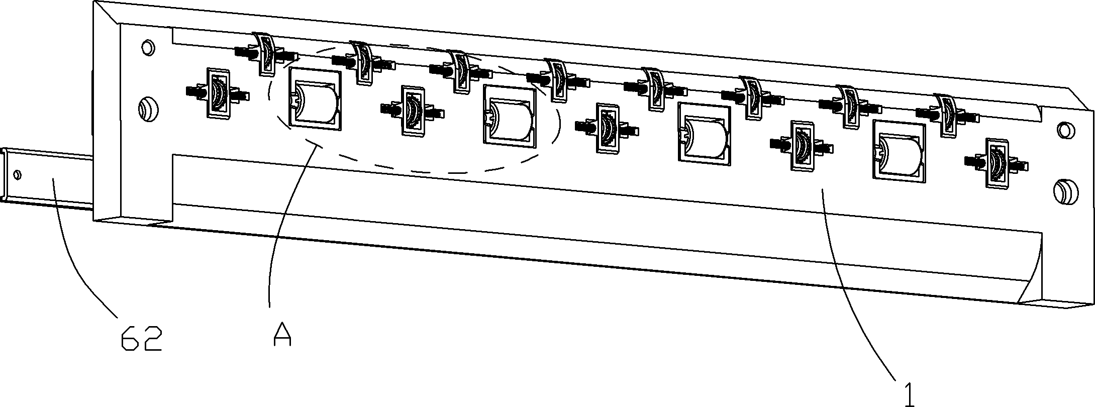
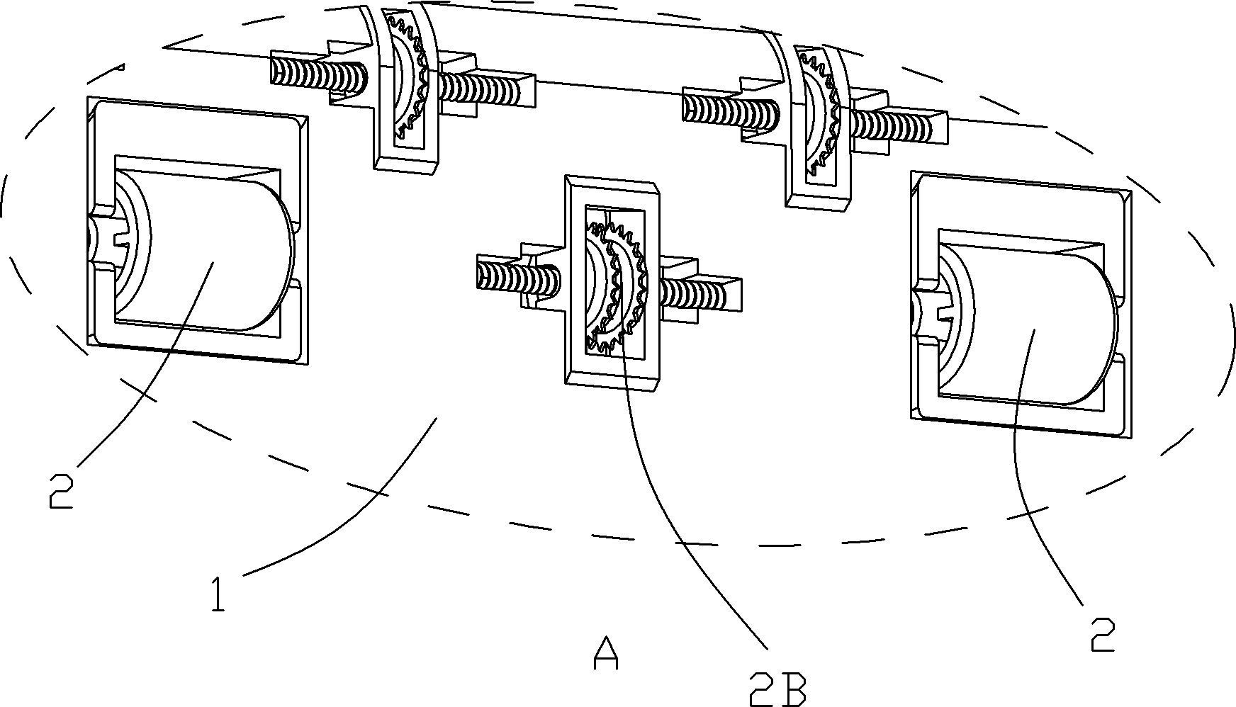
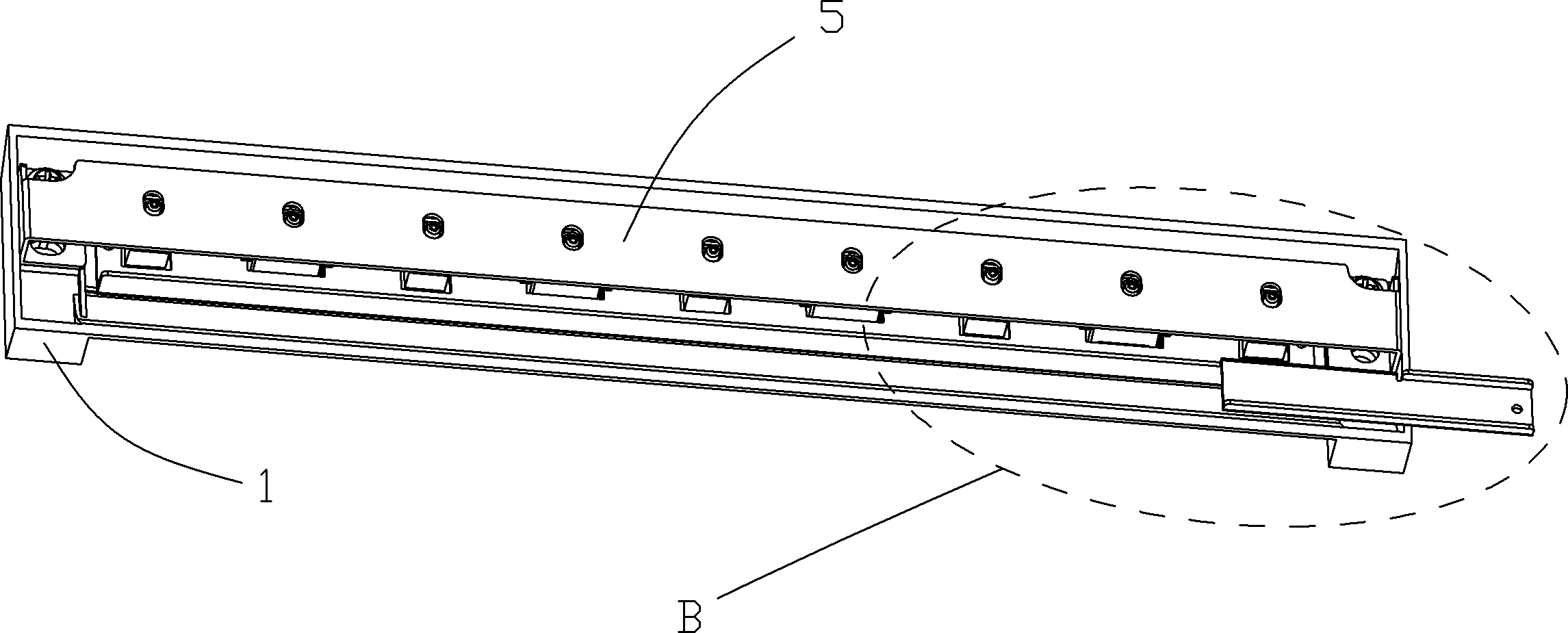
[0035] refer to Figure 1 to Figure 21 , a lifting type pickup roller mechanism of the present invention, which includes a pickup roller 2 installed on an upper paper guide base 1, the pickup roller 2 is rotatably connected to the bottom end of a pickup roller frame 3, and the pickup roller frame 3. Place it in the square hole 11 on the upper paper guide base 1. The top end of the pickup roller frame 3 is connected with a compression spring 4, and the other end of the compression spring 4 is connected to the upper paper guide base 1. The bottom end of the pressure plate 5, the pressure plate 5 is fixedly installed on the upper paper guide base 1 by screws 51, the upper paper guide base 1 is hinged with a top plate 6, considering that the thickness of the top plate 6 inside the printer is relatively thin, about 1mm Thickness, the top plate 6 is generally selected as a sheet metal part, and it is difficult to form a thick and long axis for hinges on the sheet metal part, so the ...


PUM


Abstract

The invention discloses a lift type pickup roller mechanism comprising a pickup roller which is arranged on an upper paper guiding base, wherein the pickup roller is connected at the bottom end of a pickup roller carrier, the pickup roller carrier is placed in a square hole on the upper paper guiding base, the top end of the pickup roller carrier is connected with a pressure spring, the other end of the pressure spring is connected at the bottom end of a pressure plate on the upper paper guiding base in a propping manner, the upper paper guiding base is hinged with a top plate, the top plate is provided with a through groove through which the pickup roller carrier can pass, the side wall of the pickup roller carrier is provided with a support lug, and the support log is placed on the edge of the through groove; and the top plate is also provided with a strip-type plate which can cause the top plate to drive the pickup roller carrier and the pickup roller arranged on the pickup roller carrier to turn over and lift under the driving action of a driving mechanism. The lift type pickup roller mechanism disclosed by the invention can cause the pickup roller to be far away from a print medium when a printer delivers paper, and can prevent the pickup roller from scratching an ink spot on the print medium, thus the printing quality is improved; and the lift type pickup roller mechanism disclosed by the invention has a simple, reasonable and compact structure, is convenient to mount and is low in cost.

Description

technical field [0001] The invention relates to a lifting type pickup wheel mechanism, which belongs to the field of printer equipment design and manufacture. Background technique [0002] On the printer, in order to increase the paper-pulling force of the printer’s paper-guiding device on the printing medium during the paper-guiding work, the pickup wheel is generally used as its paper-guiding mechanism, but for inkjet printers that output paper from the same paper inlet, The main board inside the printer controls the opening and closing of the nozzle on the printer nozzle to spray ink dots on the printing medium to form the required printing information. When the paper is output after printing, the ink dots on the printing medium are not dry. If the printing medium is directly Through the pickup roller, because the pickup roller has a large contact area with the printing medium, it will inevitably guide the paper and scratch the ink dots on the printing medium, which will ...

Claims


Application Information

Patent Timeline
Patent Type & Authority Patents(China)
IPC IPC(8): B41J11/00
Inventor 覃慧敏张健国梁岐江
Owner KONG YUE ELECTRONICS & INFORMATION IND XIN HUI
Features
  • R&D
  • Intellectual Property
  • Life Sciences
  • Materials
  • Tech Scout
  • Unparalleled Data Quality
  • Higher Quality Content
  • 60% Fewer Hallucinations
Learn More