
Automatic wallpaper gluing machine

A gluing machine and wallpaper technology, applied in coatings, devices for coating liquid on the surface, decorative arts, etc., can solve problems such as bad leakage and achieve high dimensional accuracy

Inactive Publication Date: 2016-03-23
KYOKUTO SANKI CO LTD
View PDF6 Cites 0 Cited by
  • Summary
  • Abstract
  • Description
  • Claims
  • Application Information

AI Technical Summary

Problems solved by technology

[0025] In addition, the subject of the present invention is also to solve the problems of the conventional metal frame side plate part due to the coating and the problem of electric leakage when not grounded.

Method used


Image

  • Automatic wallpaper gluing machine
  • Automatic wallpaper gluing machine
  • Automatic wallpaper gluing machine

Examples


Embodiment Construction

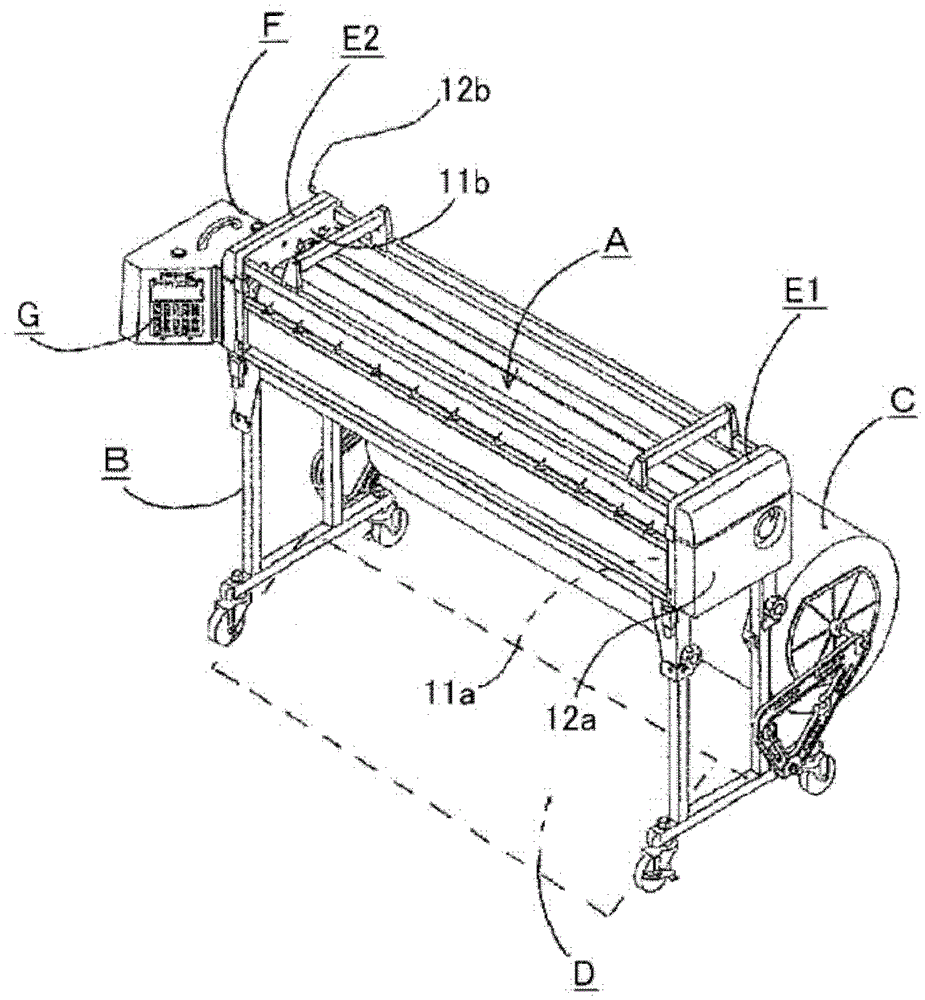
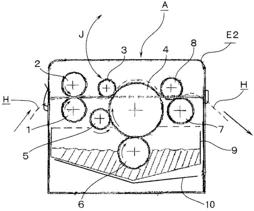
[0077] In the present invention, for example figure 1 , figure 2 The exemplified automatic wallpaper gluing machine applies glue to the back of a sheet-shaped wallpaper by the operation of a plurality of rollers including the above-mentioned gluing roller and glue amount adjusting roller.

[0078] Of course, if figure 1 As shown, the display / operation unit G and the drive unit F may be detachably attached as a box form, or may be in various conventional forms other than this.

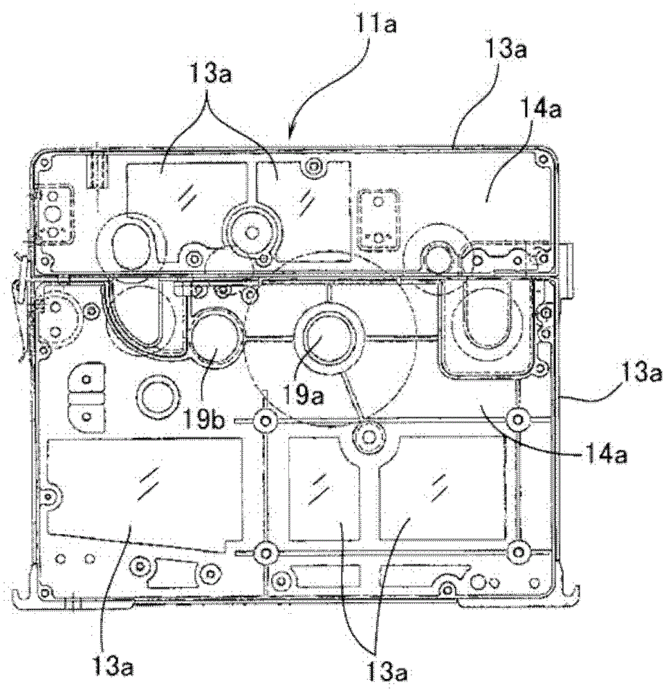
[0079] In the automatic wallpaper gluing machine of the present invention, for example figure 2 Illustrative example of bearing a plurality of rollers with both ends figure 1 In such a pair of frame side plate parts E1, E2, there are roller support plate parts 11a, 11b and resin cover parts 12a, 12b, and each roller support plate part 11a, 11b is a resin part and a metal part passing through the roller facing side. It is formed by the composite integration of the framework.

[0080] image 3 and...


PUM


Abstract

The present invention provides an automatic wallpaper gluing machine. In the automatic wallpaper gluing machine, high dimensional accuracy can be ensured while realizing light weight. Glue is applied to the back of the sheet-like wallpaper material by the operation of a plurality of rollers including a gluing roller and a glue adjustment roller, wherein a pair of frame side plates pivotally support the plurality of rollers at both ends The part respectively has a roller support plate part and an outer resin cover part, and the roller support plate part is formed by compounding and integrating the resin part (13a) and the metal frame (14a) on the opposite side of the roller, and the metal frame (14a ) is provided with a plurality of bearing holes for the rollers; a bearing hole for driving the transmission gear; and a wall and a lightening hole for ensuring the dimensional accuracy between the bearing holes.

Description

technical field [0001] The invention relates to an automatic wallpaper gluing machine. Background technique [0002] Conventionally, there is known an automatic glue applicator that automatically applies a predetermined amount of glue to the back surface of wallpaper, which is a wall decoration material (cloth). For example, figure 1 An example of the appearance of an automatic glue applicator is shown, but it generally consists of, for example, the following parts: a main body A built in a glue tank; a leg B supporting the main body A; the wallpaper roll C on the rear side; and the gummed wallpaper carrier D arranged on the front side of the main body A. [0003] The wallpaper sent out from the wallpaper roll C is glued on the back side of the main body A, and is guided to the gummed wallpaper carrier D as shown by the arrow in the figure. [0004] In the main body A, a pair of frame side plate parts E1 and E2 are provided, and a plurality of rollers for gluing are rotat...

Claims


Application Information

Patent Timeline
Patent Type & Authority Patents(China)
IPC IPC(8): B44C7/04
CPCB05C17/02B44C7/02B44C7/04
Inventor 吉田哲士清水保博山本润
Owner KYOKUTO SANKI CO LTD
Learn More